
Self-sucking type injection booster

A booster and syringe technology, applied in dilators, medical devices, obstetrics and gynecology devices, etc., can solve the problems of difficult to accurately control the amount of liquid and laborious liquid inhalation.

Pending Publication Date: 2020-05-12
淄博科创医疗仪器有限公司
View PDF1 Cites 4 Cited by
  • Summary
  • Abstract
  • Description
  • Claims
  • Application Information

AI Technical Summary

Problems solved by technology

However, the force-reducing operating system of this booster is realized by pulling the trigger, and then through the transmission of parts such as chain plates and shift forks, and the force-reducing operating system can only be used for liquid injection. The operator needs to hold the handle of the gun body with one hand, hold the plunger rod and drive plate with the other hand, and pull firmly in the direction away from the barrel to draw the liquid into the syringe
Therefore, the suction of liquid is still relatively laborious, and the amount of liquid sucked is not easy to control accurately

Method used


Image

  • Self-sucking type injection booster
  • Self-sucking type injection booster
  • Self-sucking type injection booster

Examples


Embodiment Construction

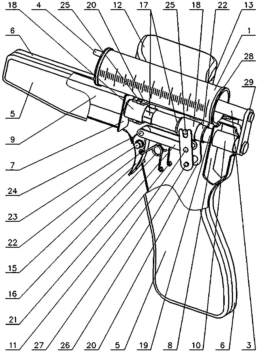
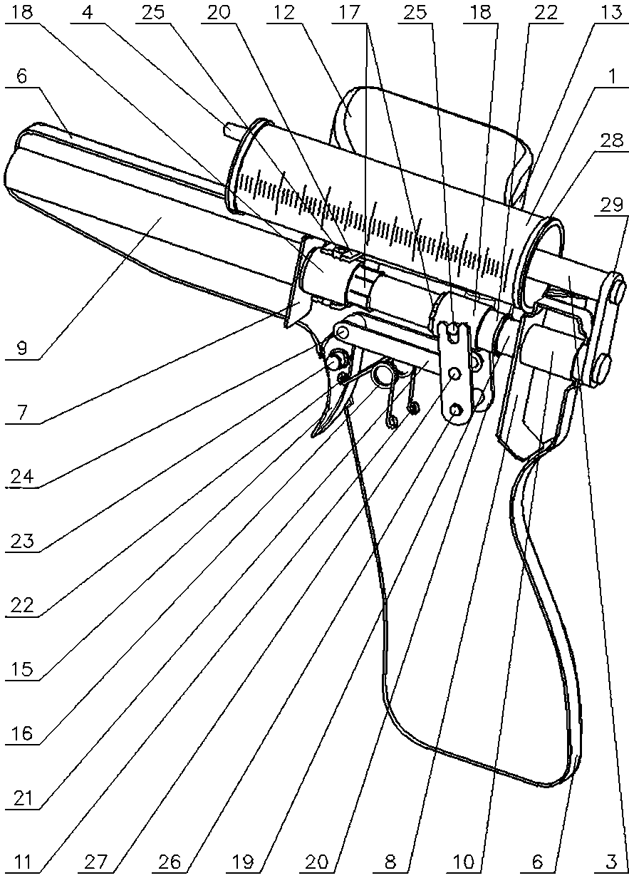
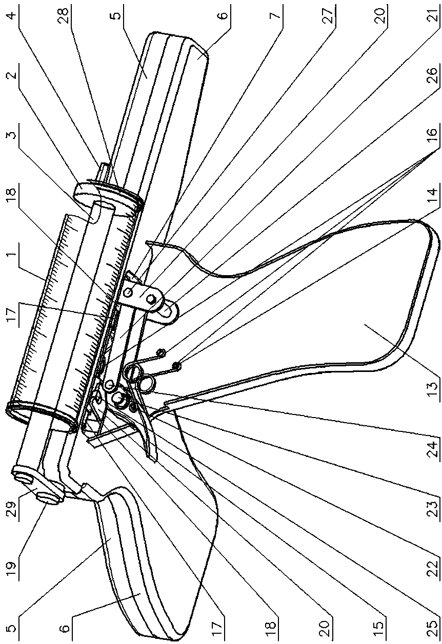
[0020] 1. Injection tube 2, plunger 3, plunger rod 4, conical tube 5, gun shell Ⅰ 6, gun shell Ⅱ 7, support plate Ⅰ 8, support plate Ⅱ 9, bushing Ⅰ 10, bushing Ⅱ 11, pin Shaft Ⅰ 12. Gun case Ⅲ 13. Gun case Ⅳ 14. Pin shaft Ⅱ 15. Trigger 16. Spring 17. Clamping sleeve 18. Booster sleeve 19. Booster rod 20. Fork 21. Chain piece 22. Pin shaft Ⅲ 23. Trigger shaft 24. Chain pin 25. Pin shaft Ⅳ 26. Fork shaft 27. Pin shaft Ⅴ 28. Clamp 29. Transmission plate.

[0021] exist Figure 1-Figure 7 In the shown embodiment: the injection tube 1 is in a transparent state, one end is closed, and the outer circles of both ends are provided with convex shoulders, and the two sides of the outer cylindrical surface of the injection tube 1 are arranged along the length direction of the injection tube 1. The scale line at the end; the closed end of the injection tube 1 protrudes a section of conical tube 4 outwards, and the conical tube 4 is located on the symmetrical plane of the scale line on bot...


PUM


Abstract

The invention provides a self-sucking type injection booster. The self-sucking type injection booster is characterized in that a support plate and a sleeve tube are arranged in an inner cavity of a gun body I; a circular arc groove is formed in the upper part of the gun body I, and a gun body II is fixed to the outer surface of a gun shell II; the two ends of a trigger shaft provided with a trigger are separately supported on the gun body I and the gun body II; the ends of both of springs are separately hanged on a pin shaft I of the gun body I and a pin shaft II of the gun body II while the other ends of both of springs are separately hanged on a pin shaft III of the trigger and penetrate through a support plate II, and an extension end of a boosting rod sleeved with two clamping sleevesand two boosting sleeves is inserted into a sleeve tube I; shifting fork shafts fixed with a shifting forks are separately supported in the middles of the gun body I and the gun body II; pin shafts IVof the two boosting sleeves are separately positioned in U-shaped grooves of the shifting forks; one end of a corresponding hinged piece is hinged in the middle of the corresponding shifting fork while the other ends of the hinged pieces are hinged at the two ends of a chain pin; an injection tube is mounted in the circular arc groove of the gun body I, and one end, equipped with a plunger, of aplunger rod is inserted into the injection tube while the other end is connected with the end part of the boosting rod. The self-sucking type injection booster disclosed by the invention has the advantages of being light and convenient in operation and easy for accurately controlling liquid injection volume and liquid sucking volume.

Description

technical field [0001] The invention provides a self-priming injection booster, which belongs to the field of medical equipment and equipment, and is mainly used for boosting and pressurizing when injecting liquid into a patient, and can also be used for dispensing medicine before infusion. Background technique [0002] When the parturient gives birth, in order to shorten the labor process and reduce the pain of the parturient, the disposable cervical dilation balloon is generally placed in the uterus and vagina of the parturient, and then the liquid is slowly injected into the disposable cervical dilation balloon through the infusion tube to gradually expand it. , so as to play the role of dilating the cervix and vagina, so as to facilitate the smooth delivery of the fetus. [0003] At present, the commonly used injection booster devices are mostly plunger syringes, which need to be manually pushed by nurses to complete the injection input of liquid, which is labor-intensiv...

Claims


Application Information

Patent Timeline
Patent Type & Authority Applications(China)
IPC IPC(8): A61M29/04A61B17/42
CPCA61B17/42A61B2017/4225A61M29/02A61M2210/1433A61M2210/1475A61M2210/005
Inventor 张同合孙传祝孙乐乐
Owner 淄博科创医疗仪器有限公司
Learn More