Film and television shooting project camera shooting unmanned aerial vehicle

A technology of drones and cameras, applied in the field of camera equipment, can solve problems such as unsteady landing of drones, inflexible camera control, and failure to achieve shooting effects, so as to achieve good camera effects, best shooting effects, and avoid breakage Effect

Inactive Publication Date: 2020-05-08
ZIBO VOCATIONAL INST
View PDF0 Cites 2 Cited by
  • Summary
  • Abstract
  • Description
  • Claims
  • Application Information

AI Technical Summary

Problems solved by technology

[0003] Aiming at the deficiencies of the prior art, the present invention provides a camera drone for film and television shooting projects, which has a better camera effect and strong stability during the flight movement of the drone, and greatly reduces the phenomenon of camera shake, which can It achieves better shooting effect, is easy to control, and can complete shooting from some special angles, which can ensure the vibration reduction performance of the drone when it lands, so as to complete the protection effect on the inside of the drone and avoid the outrigger of the drone. Fracture and other advantages, solve the current process of installing a camera on a drone for shooting, because the drone will shake during the moving process, which will cause the camera to shake during the shooting process, so it cannot achieve better shooting As a result, although today's drones can meet the requirements of high-altitude photography to a certain extent, the control of the camera is not flexible, and it is impossible to complete shooting from some special angles. If the man-machine cannot land smoothly, it may cause damage to the inside of the drone. In the long run, it may cause the outrigger of the drone to break.

Method used


Image

  • Film and television shooting project camera shooting unmanned aerial vehicle
  • Film and television shooting project camera shooting unmanned aerial vehicle
  • Film and television shooting project camera shooting unmanned aerial vehicle

Examples


Embodiment Construction

[0023] The following will clearly and completely describe the technical solutions in the embodiments of the present invention with reference to the accompanying drawings in the embodiments of the present invention. Obviously, the described embodiments are only some, not all, embodiments of the present invention. Based on the embodiments of the present invention, all other embodiments obtained by persons of ordinary skill in the art without making creative efforts belong to the protection scope of the present invention.

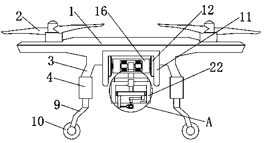
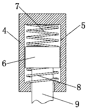
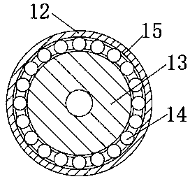
[0024] see Figure 1-5 , a camera drone for film and television shooting projects, including a drone body 1 and a camera 29, rotors 2 are installed on both sides of the top of the drone body 1, and fixed rods are fixedly connected to both sides of the bottom of the drone body 1 3. The bottom end of the fixed rod 3 is provided with a support frame 9, the middle part of the bottom of the drone body 1 is fixedly connected with a fixed frame 11, the inner side wal...


PUM


Abstract

The invention relates to the technical field of camera equipment and discloses a film and television shooting project camera shooting unmanned aerial vehicle, which comprises an unmanned aerial vehicle body and a camera, rotor wings are installed on the two sides of the top end of the unmanned aerial vehicle body; fixed rods are fixedly connected to the two sides of the bottom end of the unmannedaerial vehicle body; a support frame is arranged at the bottom end of each fixed rod; a fixing frame is fixedly connected to the middle of the bottom end of the unmanned aerial vehicle body; fixing discs are fixedly connected to the two side walls of the inner side of the fixing frame; rotating discs are rotatably connected to the inner sides of the fixing discs; a rotating frame is connected between the two rotating discs through a connecting column; and a sliding column is rotatably connected into the rotating frame. According to the film and television shooting project camera shooting unmanned aerial vehicle, the camera shooting effect of the unmanned aerial vehicle in the flight moving process is good, the stability is high, the camera shaking phenomenon is greatly reduced, shooting atsome specific angles can be completed, the vibration reduction performance of the unmanned aerial vehicle in the landing process can be guaranteed, and therefore the protection effect on the interiorof the unmanned aerial vehicle is completed.

Description

technical field [0001] The invention relates to the technical field of camera equipment, in particular to a video camera drone. Background technique [0002] At present, in the process of installing a camera on a UAV for shooting, because the UAV will shake during the movement process, which will cause the camera to shake during the shooting process, so it cannot achieve a good shooting effect. Today's UAV Although it can meet the requirements of high-altitude photography to a certain extent, the control of the camera is not flexible, and it is impossible to complete the shooting of some special angles. During the landing process of the UAV, the UAV may not be able to land smoothly due to the force. It may cause damage to the inside of the UAV, and in the long run, it may cause the outriggers of the UAV to break. For this reason, we propose a camera UAV for film and television shooting projects. Contents of the invention [0003] Aiming at the deficiencies of the prior ar...

Claims


Application Information

Patent Timeline
IPC IPC(8): B64D47/08B64C25/62
CPCB64D47/08B64C25/62B64U30/20B64U2101/30B64U10/10
Inventor 刘心怡
Owner ZIBO VOCATIONAL INST
Why Eureka
Try Eureka