Method for preventing trash holding device from being attached to and wound by sewage

A technology of dirt and trash racks, which is applied in the field of hydraulic structure trash control equipment, can solve the problems of rotary mechanical device dirt stuck, difficult to determine the size and structure of dirt cleaning teeth, and increase operating costs, so as to avoid further waste The effect of increased water hydraulic loss, good industrial application value, and eliminating the need for cleaning procedures

Inactive Publication Date: 2020-04-21
武汉博隆恩特科技有限公司
View PDF0 Cites 0 Cited by
  • Summary
  • Abstract
  • Description
  • Claims
  • Application Information

AI Technical Summary

Problems solved by technology

Due to the various forms of dirt in the river, it is difficult to determine the size and structure of the cleaning teeth, and the rotary mechanical device is easy to be stuck by the dirt and cause shutdown; the above-mentioned dirt blocking and cleaning devices with rotation and rotation functions also consume power energy , additional operating costs

Method used


Image

  • Method for preventing trash holding device from being attached to and wound by sewage
  • Method for preventing trash holding device from being attached to and wound by sewage
  • Method for preventing trash holding device from being attached to and wound by sewage

Examples


Embodiment 1

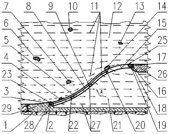
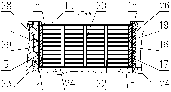
[0032] A method to prevent the grid-type trash-stopping device of the river channel water inlet from being attached and entangled by dirt, such as figure 1 As shown, including grid type trash rack 20 and auxiliary facilities: upstream grid pier 2 and downstream grid pier 17, grid type trash rack 20 is composed of grid bar 8, supporting beam 22, upper beam 15, lower beam 5, upstream The side beam 23 and the downstream side beam 19 are composed, the upstream grid pier 2 is composed of the upstream grid groove 28 buried on the upstream grid pier 2 and the upstream grid pier body 29, and the downstream grid pier 17 is composed of the downstream grid pier buried on the downstream grid pier 17. Groove 18 and downstream pier body 26 are formed. Such as figure 2 As shown, the upstream end of the grid-type trash rack 20 is inserted into the upstream grid groove 28 buried on the upstream grid pier 2 through the upstream flange 3 of the upstream side beam 23, and the downstream end of ...

Embodiment 2

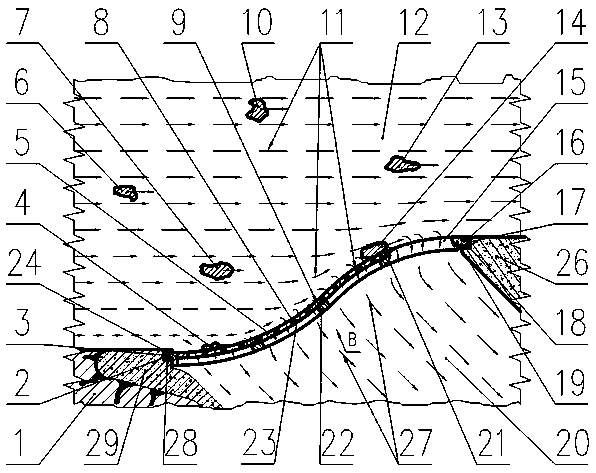
[0043] A method to prevent the orifice-type sewage blocking device of the river channel water inlet from being attached and entangled by dirt, such as image 3 As shown, it includes orifice type trash rack 21 and ancillary facilities: upstream grid pier 2 and downstream grid pier 17. 24 and the downstream side beam 19, the upstream grid pier 2 is composed of the upstream grid groove 28 buried on the upstream grid pier 2 and the upstream grid pier body 29, and the downstream grid pier 17 is composed of the downstream grid groove 18 buried on the downstream grid pier 17 and the downstream pier body 26. Such as Figure 4As shown, the upstream end of the orifice trash rack 21 is inserted into the upstream grid groove 28 of the upstream pier 2 through the upstream flange 3 of the upstream side beam 24, and the downstream end of the orifice trash rack 21 passes through the downstream side of the downstream side beam 19. The flange 16 is inserted into the downstream grid groove 18 ...


PUM


Abstract

The invention discloses a method for preventing a trash holding device from being attached to and wound by sewage. Methods of hydromechanics measuring and theoretical calculation, a hydromechanics model test and the like are used for collecting water flow state, water surface air pressure and wave pressure data of an arranging area of the trash holding device, trash racks and accessory facilitiesthereof forming the trash holding device serve as a whole body, according to the above data, in combination with hydromechanics and tribology methods and principles, design and manufacturing are carried out, the model tests are used for verifying and optimizing, the trash holding device can use thrust generated by water flow speed vectors, water surface air pressure vectors and wave pressure vectors to overcome friction resistance between the sewage and the trash holding device, and it is ensured that the sewage, in contact with the trash holding device, required to be intercepted is flushed away through the water flow, wind and waves, flows to a set area, and cannot be attached to and wound on the trash holding device. The method has the advantages of being free of trash cleaning program,reducing water conservancy facility running cost and safety hidden dangers, prolonging the service life of hydraulic machines and the like.

Description

technical field [0001] The invention relates to the technical field of hydraulic structure trash-stopping equipment, in particular to a method for preventing a trash-blocking device from being attached and entangled by dirt during a trash-blocking operation. Background technique [0002] In the hydraulic structure of water intake and delivery, the trash control device is an indispensable equipment. Trash racks are generally required at the water inlets of pumping stations, hydropower stations, reservoirs, urban water supply, and ship lock water delivery corridors to block animals and plants, industrial and agricultural waste, and domestic garbage that are entrained in the water flow ( Hereinafter referred to as dirt), so that harmful dirt will not flow into the water diversion channel, so as to protect the unit, gates, valves and pipelines from damage, and ensure the efficient and safe operation of the unit and other equipment and structures. [0003] The trash rack in the ...

Claims


Application Information

Patent Timeline
Patent Type & Authority Applications(China)
IPC IPC(8): E02B5/08E02B15/06
CPCE02B5/08E02B15/06
Inventor 江浩涂波
Owner 武汉博隆恩特科技有限公司
Why Eureka
Try Eureka