Centrifugal oil-gas separation device

A separation device, oil and gas separation chamber technology, applied in the direction of machine/engine, crankcase ventilation, mechanical equipment, etc., can solve the problems of high manufacturing cost, long route, large space occupied by external pipelines, etc., to achieve smooth gas passage and overall structure. Compact, non-interfering effect of gas channels

Pending Publication Date: 2020-04-17
HEFEI WAL FUEL SYST CO LTD
View PDF0 Cites 1 Cited by
  • Summary
  • Abstract
  • Description
  • Claims
  • Application Information

AI Technical Summary

Problems solved by technology

Because the gas is relatively light, the law is that it is easy to go up, but it is difficult to go down. Therefore, the disadvantage of the existing technology is that it does not conform to the law of gas operation, and it may cause the separated clean gas to reverse or contain oil. Gas is discharged directly from the gas outlet
[0004] In addition, the air inlet port of the current centrifugal oil-gas separator is on the upper end of the shell and the air outlet port is on the side or bottom of the shell, so that the external pipe takes up a lot of space and cannot be used in occasions where the installation space is small
At the same time, because the air outlet channel is arranged under or on the side of the shell, the route is longer, so the structure is more complicated, and the manufacturing cost is relatively high.

Method used


Image

  • Centrifugal oil-gas separation device
  • Centrifugal oil-gas separation device
  • Centrifugal oil-gas separation device

Examples


Embodiment Construction

[0043] In the following description of this embodiment, it should be understood that the orientations or positional relationships indicated by the words "upper", "lower", "inner", "outer", etc. are based on the orientation or positional relationships indicated in the drawings, and only It is for the convenience of describing the present invention and simplifying the description, but does not indicate or imply that the devices or elements shown must have a specific orientation, be constructed and operated in a specific orientation, and thus should not be construed as limiting the present invention.

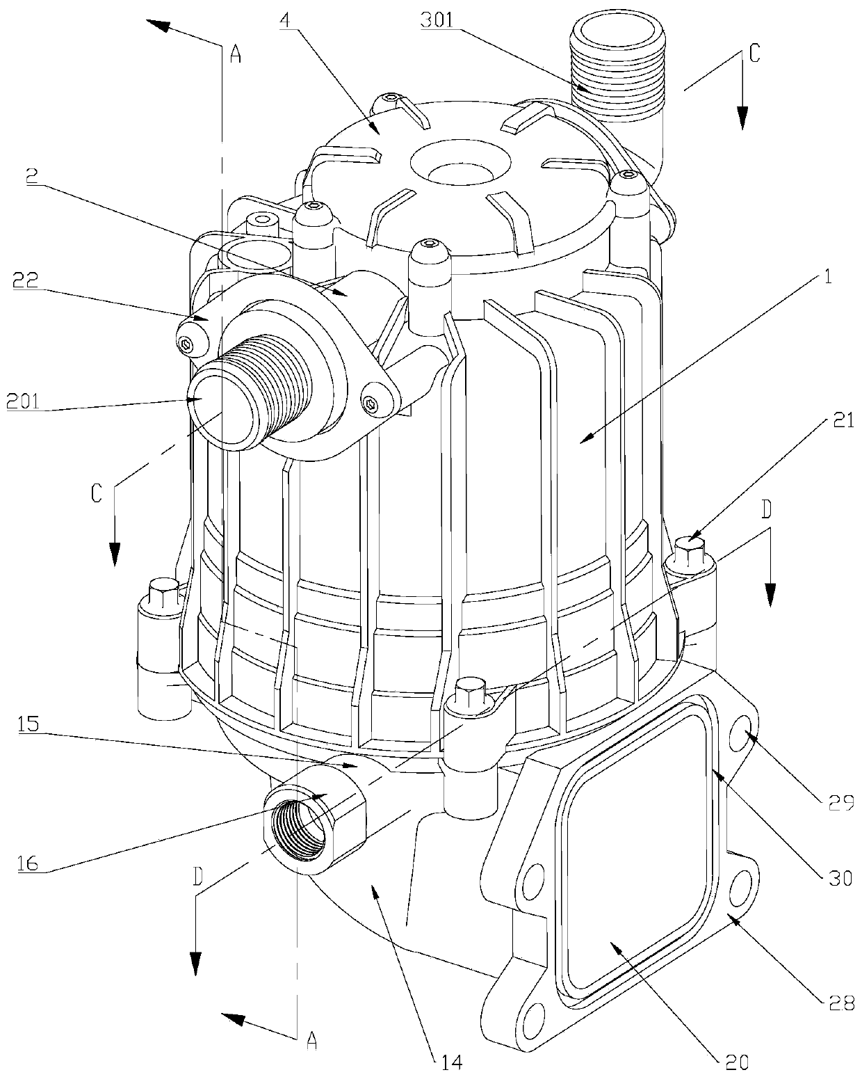
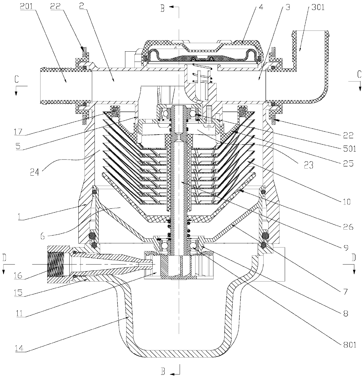
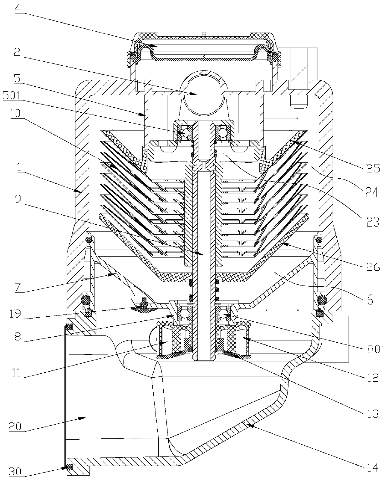
[0044] figure 1 It is a centrifugal oil and gas separation device. It consists of an outer shell 1 , an inner shell 7 , a centrifugal separation mechanism and a support seat 14 .

[0045] 1. Outer shell, inner shell, oil-gas separation chamber and oil-gas separation mechanism

[0046] The outer casing 1 is in the shape of a bell jar with one open end, the top of which is closed, ...


PUM


Abstract

The invention discloses a centrifugal oil-gas separation device. An outer shell of the device is in a bell jar shape in which the top is closed, an opening is arranged downwards, and an inner cavity is hollow. The outer shell and an inner shell are connected to form an oil-gas separation cavity for installing an oil-gas separation mechanism. An air inlet connector arranged on one side of the top of the outer shell communicates with an air inlet hole formed in the top end of the inner cavity of the outer shell and located in the inner side of a first bearing block. An air outlet connector arranged on the other side of the top of the outer shell communicates with an air outlet hole formed in the top end of the inner cavity of the outer shell and located in the outer side of the first bearingblock. A separation blade set in the oil-gas separation mechanism is sleeved with a first pressing plate at one end of a middle shaft and a second pressing plate at the other end of the middle shaftand fixed to the middle portion of the middle shaft. The air inlet hole sequentially communicates with a hollow part of an upper pressing plate and hollow structures in the middles of various blades in the separation blade set. The periphery space of the separation blade set communicates with the air outlet hole. The structure design of the centrifugal oil-gas separation device conforms to the rule that gas easily ascends, and oil molecules are heavy and are likely to descend, and the structure design is reasonable and compact.

Description

technical field [0001] The invention relates to a centrifugal oil-gas separation device and an engine equipped with the centrifugal oil-gas separation device. Background technique [0002] With the increasing requirements of automobile emission regulations in the country, in order to reduce the mobile source pollution of the engine, the requirements for the separation efficiency of the crankshaft ventilation oil-gas separator are also getting higher and higher. Conventional labyrinth oil-gas separation, filter oil-gas The separation efficiency of the separation can no longer meet the requirements. [0003] At present, the commonly used centrifugal oil-gas separator usually sets the air inlet port on the upper end of the shell, and the air outlet port is set on the side or bottom of the shell. This design makes the gas travel route from top to bottom after oil and gas separation. . Because the gas is relatively light, the law is that it is easy to go up, but it is difficult...

Claims


Application Information

Patent Timeline
IPC IPC(8): F01M13/04
CPCF01M13/04F01M2013/0422
Inventor 何顺东孙桂芝渠海洋郭珩
Owner HEFEI WAL FUEL SYST CO LTD
Why Eureka
Try Eureka