An overhead ground wire pilot lightning guide and combined electromagnetic energy dissipation device
An energy dissipation device and overhead ground wire technology, applied in circuit devices, overhead installations, emergency protection circuit devices, etc., can solve the problems of large energy during lightning strikes, threatening transformer safety, and heavy line maintenance workload, etc. The effect of improving efficiency and preventing primary side overvoltage
- Summary
- Abstract
- Description
- Claims
- Application Information
AI Technical Summary
Problems solved by technology
Method used
Image
Examples
Embodiment 1
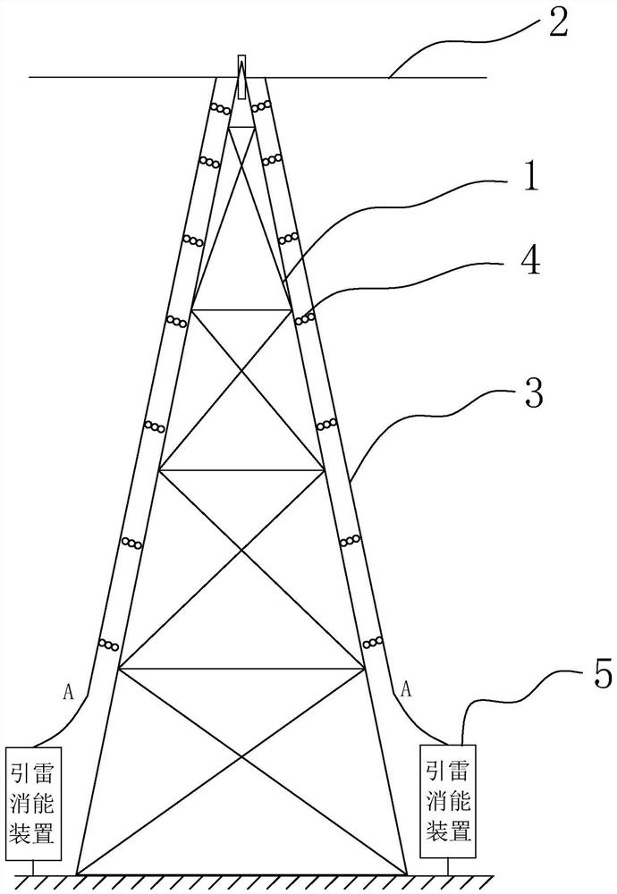
[0031] An overhead ground wire pilot lightning guide and combined electromagnetic energy dissipation device, such as figure 1 As shown, it includes an iron tower 1 , a cable 3 , a ground wire 2 erected on the iron tower 1 and an insulator 4 arranged between the cable 3 and the iron tower 1 . One end of the cable 3 is connected to the outer layer of the ground wire 2 , and the other end of the cable 3 is connected to the lightning induction device 5 .
[0032] The inner layer of the ground wire 2 is connected to the iron tower 1, including the communication line; the outer layer of the ground wire 2 is conductive and connected to the cable 3; an insulating layer is set between the inner layer and the outer layer of the ground wire 2, and the inner and outer layers of the partition are prevented from interfere with each other. The outer layer of the ground wire 2 passes through alternating current in winter, generates heat, and plays the role of melting ice.
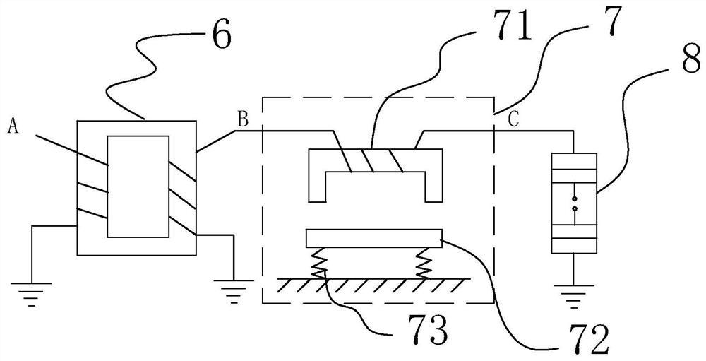
[0033] The overh...
Embodiment 2
[0046] An overhead ground wire pilot lightning guide and combined electromagnetic energy dissipating device improves the energy dissipating module 7 .
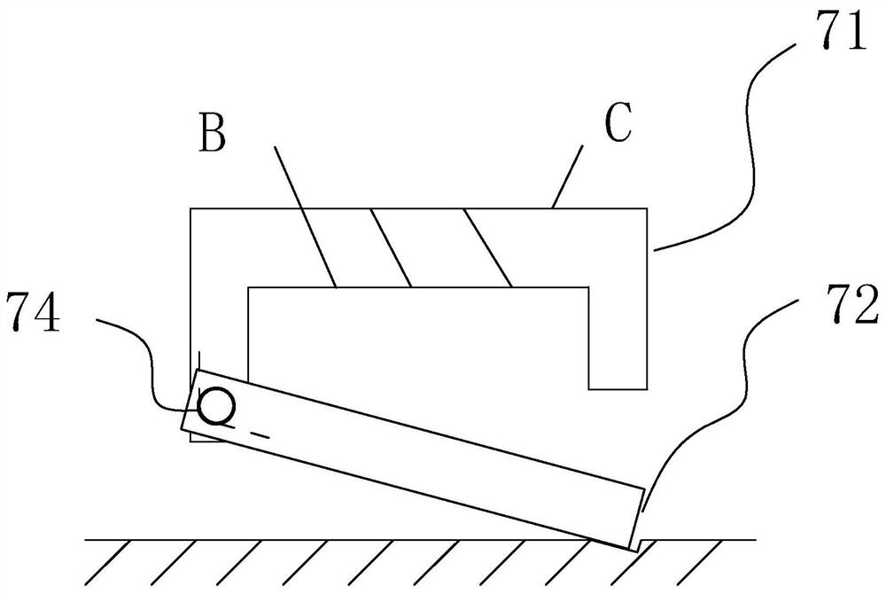
[0047] Such as image 3 As shown, the energy dissipation module 7 includes an armature reactor and a torsion spring 74, and the armature reactor includes a movable iron core 72 and a fixed iron core 71 with windings. The iron core material is silicon copper sheet, and the coil withstand voltage level is 100kV.
[0048] One end of the fixed iron core 71 and one end of the movable iron core 72 are respectively provided with mounting holes, and the torsion spring 74 is arranged in the mounting holes to connect the fixed iron core 71 and the movable iron core 72; one end of the torsion spring 74 is fixed to the movable iron core 72 The other end of the torsion spring 74 is fixedly connected with the fixed iron core 71. The other end of the movable iron core 72 leans against a fixed object, such as the ground. In this embodiment...
Embodiment 3
[0053] An overhead ground wire pilot lightning guide and combined electromagnetic energy dissipating device improves the energy dissipating module 7 .
[0054] Such as Figure 4 As shown, the energy dissipation module 7 includes an armature reactor, a fixed pulley 75 and a weight 76, and the armature reactor includes a movable iron core 72 and a fixed iron core 71 with windings. The iron core material is silicon copper sheet, and the coil withstand voltage level is 100kV.
[0055] One end of the fixed iron core 71 and one end of the movable iron core 72 are connected by a rotating shaft 77, and the other end of the movable iron core 72 is provided with a small hole, and a stay rope is arranged in contact with the top of the fixed pulley 75, and one end of the stay rope is tied to the movable iron core. On the aperture of 72, the other end of stay cord is fixedly connected with weight 76.
[0056] When lightning strikes, the voltage induced by the secondary side of the pilot ...
PUM
 Abstract
Description
Claims
Application Information
 - R&D
- Intellectual Property
- Life Sciences
- Materials
- Tech Scout
- Unparalleled Data Quality
- Higher Quality Content
- 60% Fewer Hallucinations
Browse by: Latest US Patents, China's latest patents, Technical Efficacy Thesaurus, Application Domain, Technology Topic, Popular Technical Reports.
© 2025 PatSnap. All rights reserved.Legal|Privacy policy|Modern Slavery Act Transparency Statement|Sitemap|About US| Contact US: help@patsnap.com


