
Magnetic lock

A magnetic lock and lock body technology, applied in the field of magnetic locks, can solve the problems of broken glass, damaged glass doors, affecting the appearance of glass doors, etc., and achieves the effects of firm installation, improved practicability, and simple operation.

Pending Publication Date: 2020-04-10
徐志克
View PDF0 Cites 2 Cited by
  • Summary
  • Abstract
  • Description
  • Claims
  • Application Information

AI Technical Summary

Problems solved by technology

[0003] However, the above-mentioned operation method destroys the glass by opening the glass door, and the glass door is easily damaged during the opening process.
[0004] Moreover, when the lock is installed at the opening, the lock protrudes on the glass door, which affects the beauty of the glass door.

Method used


Image

  • Magnetic lock
  • Magnetic lock
  • Magnetic lock

Examples


Embodiment

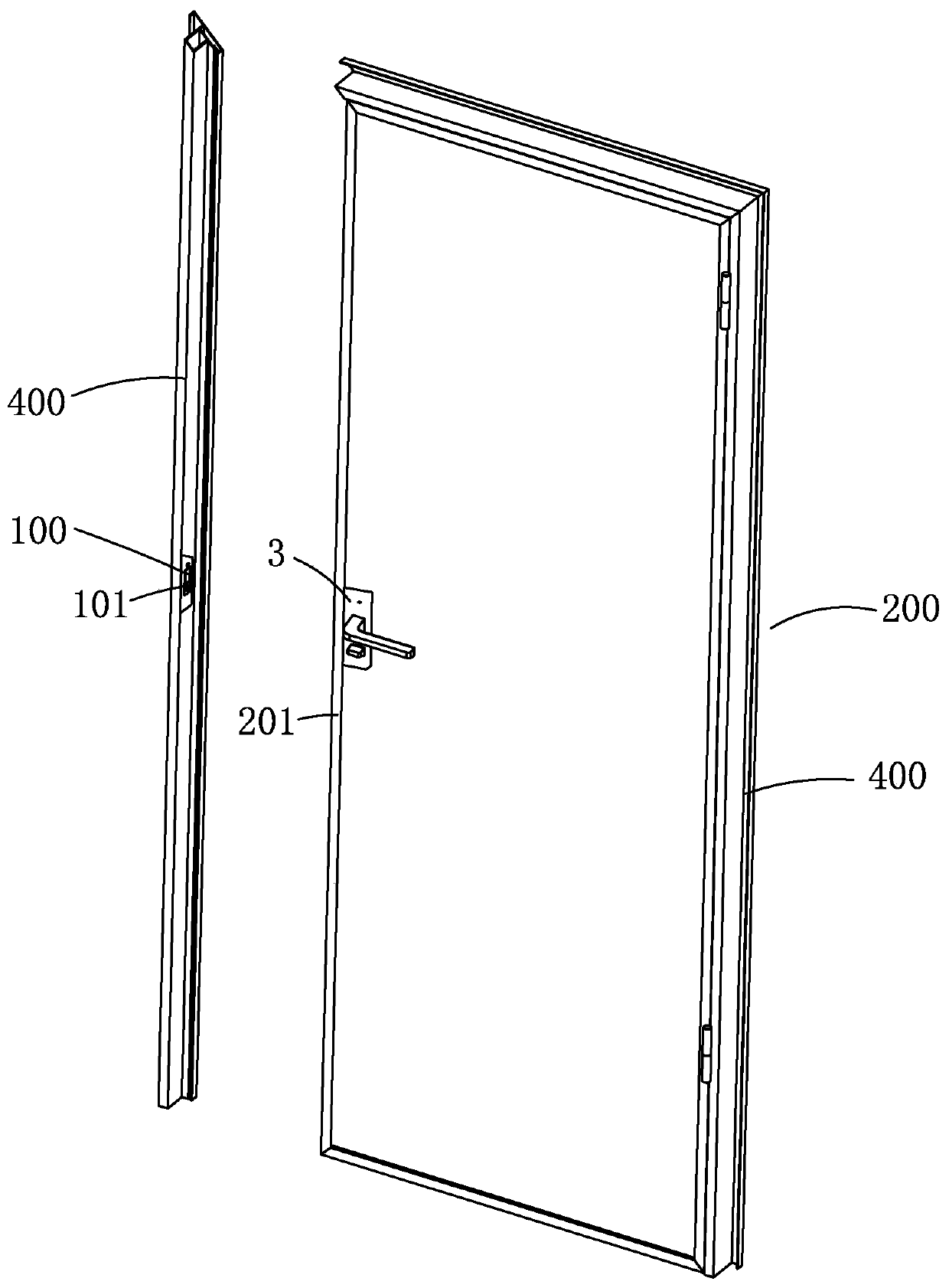
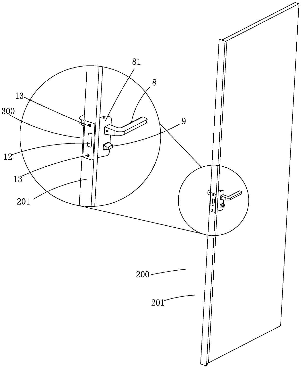
[0040] Example, combined with Figure 1 to Figure 12 As shown, a magnetic lock includes a lock body 1 , a slider 2 , a handle 8 , an anti-lock knob 9 , a panel 81 , a cover 82 , a first elastic member 10 , a second elastic member 15 and a torsion spring 16 .

[0041]The lock body 1 is an integrally formed concave lock, the depression of the lock body 1 is the clamping groove 11, the bottom of the depression is provided with a bolt entrance 12, and a bolt is provided on the periphery of the bolt entrance 12 to facilitate the passage of bolts. The bolt hole 13 of the clamping groove 11, the side wall of the lock body 1 has an active chamber 14, and the movable chamber 14 is provided with a handle rotating seat 3, an anti-lock rotating seat 4, a first push piece 5, and a second push piece 6 And limit piece 7.

[0042] The slider 2 is a concave slider 2, the side wall of the slider 2 extends into the movable cavity 14 of the lock body 1 and is close to the first push piece 5, the...


PUM


Abstract

The invention relates to a magnetic lock. The magnetic lock comprises a lock body, a clamping groove is formed in the lock body, a spring bolt inlet is formed in the position, corresponding to the clamping groove, of the lock body, a sliding block is arranged at the position, corresponding to the spring bolt inlet, of the lock body, a magnet which is used for attracting the spring bolt is arrangedin the sliding block, a handle rotating seat, a counter lock rotating seat, a first pushing piece, a second pushing piece and a limiting pieces are arranged on the side wall of the lock body, the first pushing piece is arranged on the side wall of the lock body in a rotating mode, the first pushing piece rotates to push the sliding block to stretch out and draw back, the second pushing piece is connected with the handle rotating seat, the second pushing piece rotates along with the handle rotating seat, the second pushing piece pushes the first pushing piece to rotate, the limiting piece is connected with the counter lock rotating seat, the limiting piece rotates along with the counter lock rotating seat, and the limiting piece adjusts the rotating angle and height of the first pushing piece, so that the first pushing piece and the second pushing piece are controlled to make contact or be separated. According to the magnetic lock, the lock body is provided with the clamping groove, and a glass door extends into the clamping groove with the corresponding thickness to be clamped, so that installation between a narrower door body and the lock body is completed.

Description

technical field [0001] The invention relates to a magnetic lock. Background technique [0002] When installing a door lock on a narrow door (such as a glass door with a frame) currently on the market, it is necessary to reserve an opening on the narrow door (such as a glass door with a frame), and then install a lock on the opening. [0003] However, in the above-mentioned operation mode, the glass door is damaged by opening the glass door, and the opening process is likely to cause damage to the glass door. [0004] And, lockset is installed toward opening, and lockset protrudes on the glass door, affects the attractive in appearance of glass door. Contents of the invention [0005] The purpose of the present invention is to provide a magnetic lock suitable for thinner door bodies, avoiding pre-installation of door locks on the opening of the door body, and easy to install the door locks. [0006] The purpose of the present invention is achieved like this: [0007] A m...

Claims


Application Information

Patent Timeline
Patent Type & Authority Applications(China)
IPC IPC(8): E05B47/00E05B3/00E05B17/22E05B65/00E06B3/02
CPCE05B47/00E05B3/00E05B17/22E05B65/0025E06B3/02
Inventor 徐志克
Owner 徐志克
Learn More