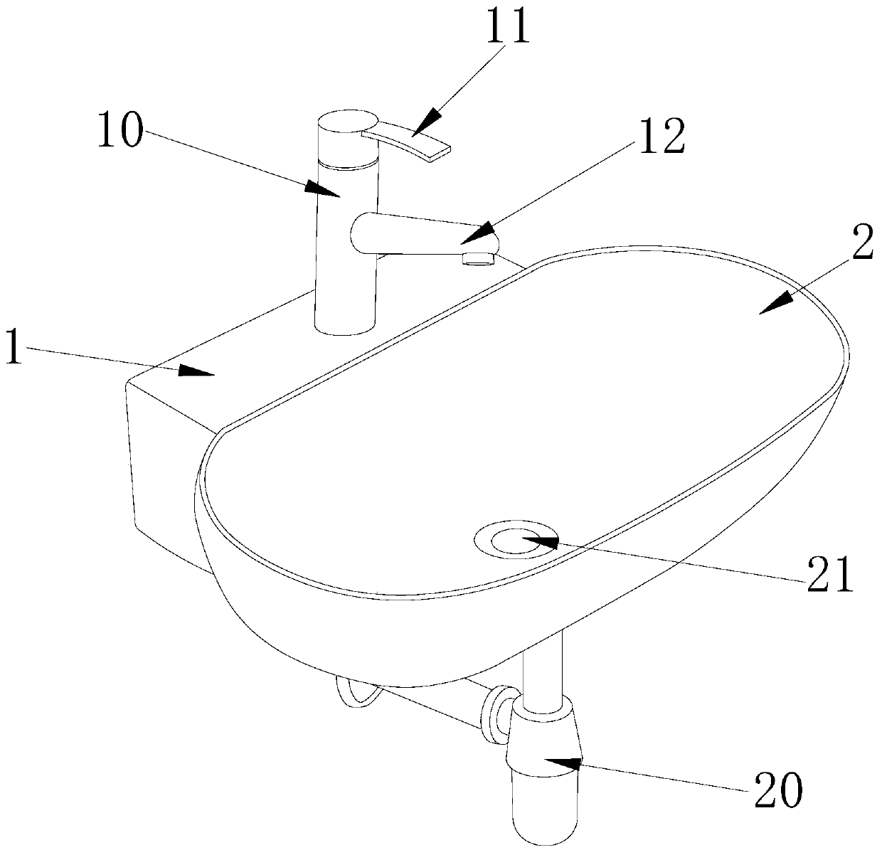
Hand basin with automatic adjustment drainer
An automatic adjustment and washbasin technology, applied in water supply installations, indoor sanitary plumbing installations, buildings, etc., can solve problems such as troublesome, difficult to clean, and blockage of sewer pipes, and achieve the effect of convenient use
- Summary
- Abstract
- Description
- Claims
- Application Information
AI Technical Summary
Problems solved by technology
Method used
Image


Examples
Embodiment 1
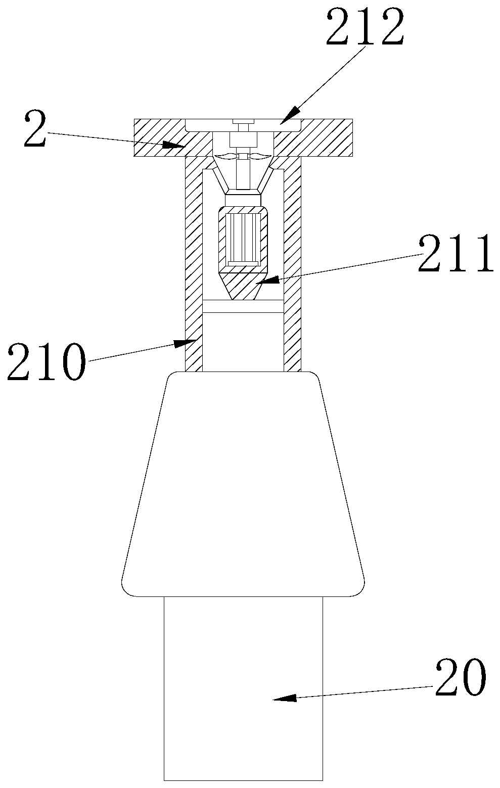
[0032] Embodiment 1: When in use, the water pressure in the hanging basin 2 is sensed by the pressure-sensitive baffle 212, and then the pressure-sensitive baffle 212 is pushed up by the hydraulic breaker 211, so that the sewage enters the downpipe 210, and the sewage is guided flow; when the pressing plate E on the pressure-sensitive baffle 212 senses that there is too much water in the hanging basin 2, the pressing plate E drives the transformer F to work, thereby pushing the baffle D to rise, and opening the top inlet of the downpipe 210; when the transformer When F is working, the transformer F drives the hydraulic breaker 211 to work at the same time. Under the push of the hydraulic device C, the support rod C1 rises upwards, thereby driving the blade C2 and the pressure-sensitive baffle 212 to rotate upwards, and at the same time drive the blade C2 cuts the hair of the sewer pipe 210 to prevent the hair from clogging the sewer pipe 210, and at the same time, it can automa...
Embodiment 2
[0033]Embodiment 2: When in use, when the amount of water in the hanging basin 2 is insufficient, but sewage diversion needs to be carried out, the pressing plate E cannot drive the hydraulic unit C to work, and at this time, it is necessary to press it manually Press the plate E to drive the transformer F to work. Driven by the transformer F, the hydraulic device C is driven to push the support rod C1 up, and at the same time, the baffle D is pushed to open the entrance of the downpipe 210 at the bottom of the hanging basin 2, and then the hydraulic breaker 211 is driven in It can also work when the water pressure is insufficient. At the same time, when the water pressure is removed, the hydraulic device C is driven by the pressing plate E to push the support rod C1 to recover, thereby driving the baffle D to block the entrance of the downpipe 210, and the hanging basin 2 is completed. closed.
[0034] The technical progress that the present invention obtains relative to the ...
PUM
 Abstract
Description
Claims
Application Information
 - R&D
- Intellectual Property
- Life Sciences
- Materials
- Tech Scout
- Unparalleled Data Quality
- Higher Quality Content
- 60% Fewer Hallucinations
Browse by: Latest US Patents, China's latest patents, Technical Efficacy Thesaurus, Application Domain, Technology Topic, Popular Technical Reports.
© 2025 PatSnap. All rights reserved.Legal|Privacy policy|Modern Slavery Act Transparency Statement|Sitemap|About US| Contact US: help@patsnap.com