
Color optical waveguide structure and display device

A waveguide structure, optical waveguide technology, applied in the direction of light guide, plane/plate light guide, light guide of lighting system, etc., can solve problems such as dispersion, difficult to control grating to respond to only one color, difficult color display, etc.

Active Publication Date: 2020-04-03
BOE TECH GRP CO LTD
View PDF6 Cites 5 Cited by
  • Summary
  • Abstract
  • Description
  • Claims
  • Application Information

AI Technical Summary

Problems solved by technology

The diffractive optical waveguide device uses a grating as the in-coupling and out-coupling element of the optical waveguide. Compared with the geometric optical waveguide using a free-form surface or film array, it is thinner and easier to mass-produce. However, it is difficult to control the grating to respond to only one color and to other The color does not respond at all, and there will be a phenomenon of dispersion. This characteristic of the grating determines that it is difficult to achieve a color display without chromatic aberration

Method used


Image

  • Color optical waveguide structure and display device
  • Color optical waveguide structure and display device
  • Color optical waveguide structure and display device

Examples


Embodiment Construction

[0040] Based on the dispersion phenomenon in the color light waveguide structure in the related art, which leads to the distortion of the transmitted image, the embodiment of the present invention provides a color light waveguide structure and a display device. In order to make the object, technical solution and advantages of the present invention more clear, the specific implementation manners of a color light waveguide structure and a display device provided by the embodiments of the present invention will be described in detail below with reference to the accompanying drawings. It should be understood that the preferred embodiments described below are only used to illustrate and explain the present invention, not to limit the present invention. And in the case of no conflict, the embodiments in the present application and the features in the embodiments can be combined with each other.

[0041] Unless otherwise defined, the technical terms or scientific terms used in the pr...


PUM


Abstract

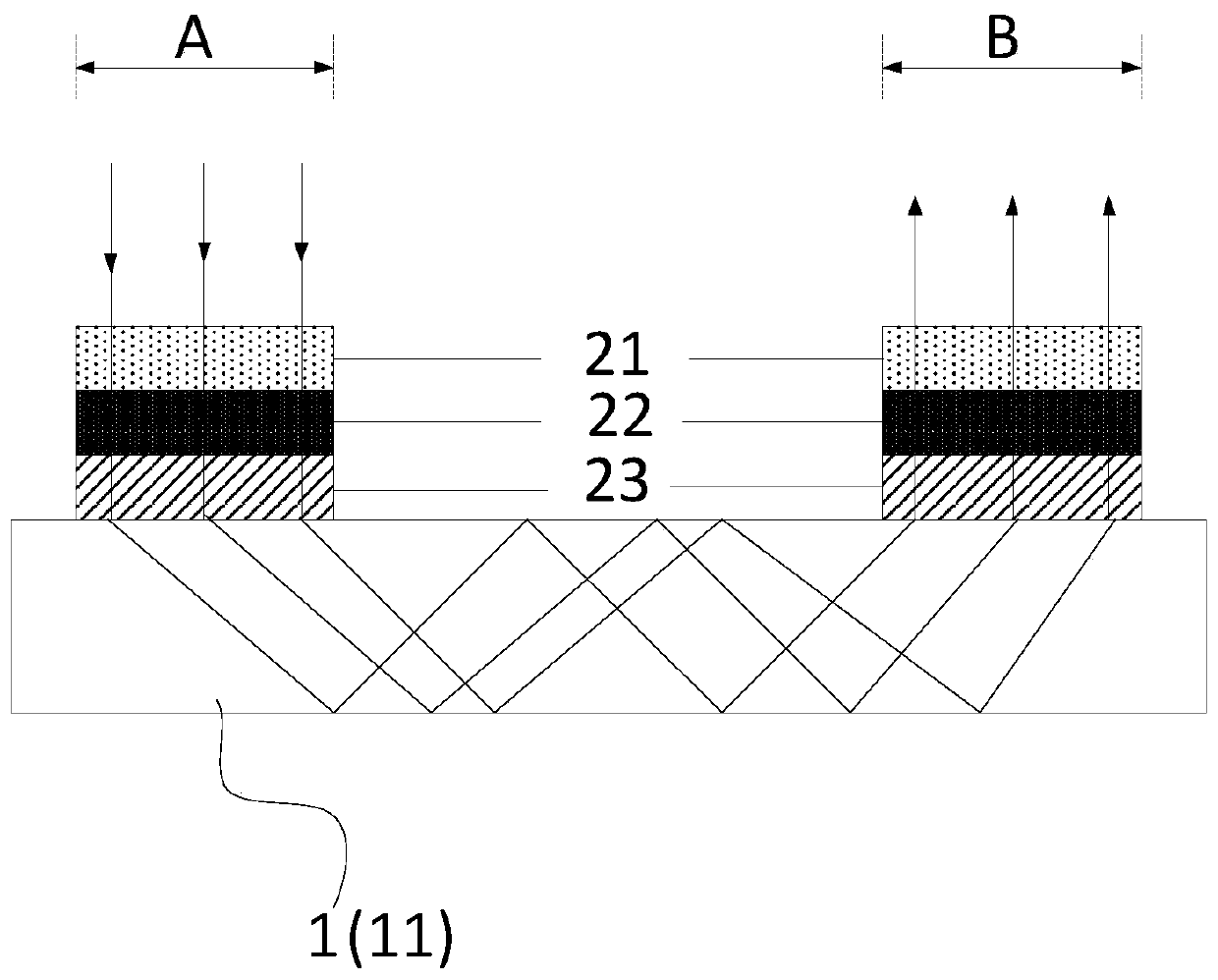
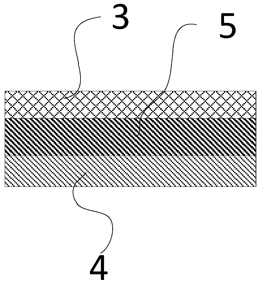
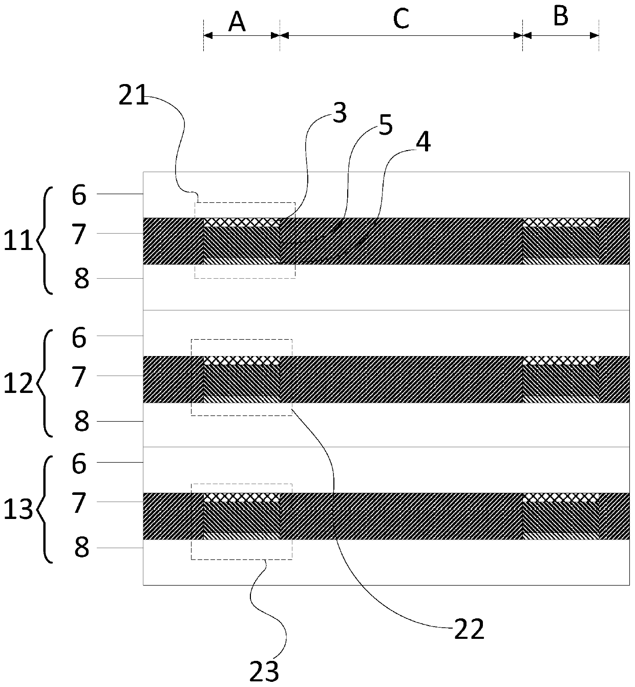
The invention discloses a color optical waveguide structure and a display device, and the structure comprises an optical waveguide which comprises a coupling-in region and a coupling-out region; the coupling-in region comprises a coupling-in grating structure and a coupling-out grating structure; the coupled-in grating structure and the coupled-out grating structure corresponding to each color arecontrolled; when the coupling-in grating structure and the coupling-out grating structure corresponding to one color are in a diffraction mode, the coupling-in grating structure and the coupling-outgrating structure are in a diffraction mode; the coupled-in grating structure and the coupled-out grating structure corresponding to other colors are in a transmission mode. Therefore, only the optical waveguides corresponding to the coupled-in grating structure and the coupled-out grating structure in the diffraction mode transmit light of corresponding colors. The optical waveguides corresponding to the coupled-in grating structure and the coupled-out grating structure in the transmission mode do not transmit light of corresponding colors, so that it is guaranteed that light of only one color is emitted in each time period, the chromatic dispersion phenomenon of the grating is relieved, and optical waveguide chromatic aberration-free color display can be achieved.

Description

technical field [0001] The invention relates to the field of display technology, in particular to a color light waveguide structure and a display device. Background technique [0002] Augmented Reality (AR, Augmented Reality) is a technology that uses virtual objects or information to augment real scenes, and is widely used in scientific research, military, industry, games, video, education and other fields. Near-eye AR display has attracted a lot of attention for its extremely high immersion. As a light and thin near-eye display device, optical waveguide near-eye display device is a mainstream solution for realizing near-eye AR display. [0003] In the related technology, a micro image display is used as the image source, and the image is projected to the optical waveguide coupling element coupled into the waveguide structure with the optical system, and after a certain distance is transmitted in the waveguide, it is projected to the human eye through the coupling element t...

Claims


Application Information

Patent Timeline
Patent Type & Authority Applications(China)
IPC IPC(8): G02B6/00G02B27/00G02F1/1335
CPCG02B6/0026G02B6/005G02B27/0093G02F1/133504
Inventor 田依杉孟宪芹王维梁蓬霞王方舟闫萌薛高磊陈小川
Owner BOE TECH GRP CO LTD
Learn More