
Positioning structure of joint encoder of robot, joint of robot and robot

A technology of robot joint and positioning structure, applied in the field of encoder positioning, can solve the problems of complex robot joint structure, inconvenient debugging work, unsatisfactory encoder installation accuracy, etc., to shorten the dimension chain, facilitate debugging and trimming, and improve installation. The effect of precision

Inactive Publication Date: 2020-04-03
MH ROBOT & AUTOMATION
View PDF0 Cites 0 Cited by
  • Summary
  • Abstract
  • Description
  • Claims
  • Application Information

AI Technical Summary

Problems solved by technology

However, the robot joint structure is relatively complex, which puts forward higher requirements for the installation accuracy of the encoder.
The encoder consists of a reading head and a code disc. It is usually designed so that the reading head is fixedly connected to the joint shell of the robot. The code disc is installed on the input or output side of the reducer, showing a state of separate installation. The installation accuracy of the encoder is often variable. satisfactory
In addition, making the encoder into a separate module can realize separate test and adjustment before joint installation, and the form of separate installation will bring great inconvenience to the subsequent debugging work

Method used


Image

  • Positioning structure of joint encoder of robot, joint of robot and robot

Examples


Embodiment Construction

[0022] The present disclosure will be further described below in conjunction with the accompanying drawings and embodiments.

[0023] It should be noted that the following detailed description is exemplary and intended to provide further explanation of the present disclosure. Unless defined otherwise, all technical and scientific terms used herein have the same meaning as commonly understood by one of ordinary skill in the art to which this disclosure belongs.

[0024] It should be noted that the terminology used herein is only for describing specific embodiments, and is not intended to limit the exemplary embodiments according to the present disclosure. As used herein, unless the context clearly dictates otherwise, the singular is intended to include the plural, and it should also be understood that when the terms "comprising" and / or "comprising" are used in this specification, they mean There are features, steps, operations, means, components and / or combinations thereof.

...


PUM


Abstract

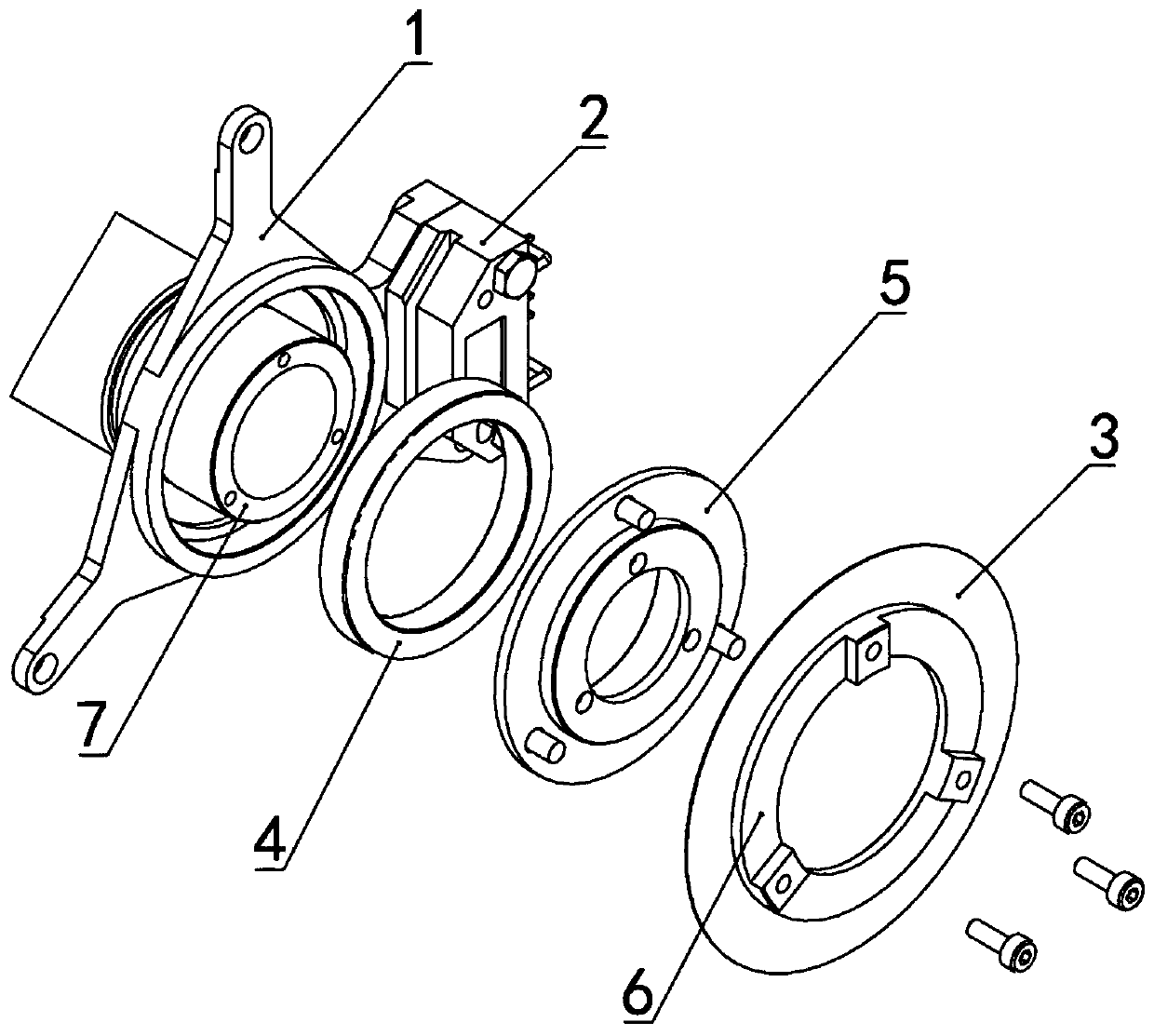
The invention provides a positioning structure of a joint encoder of a robot, a joint of the robot and the robot. The positioning structure of the joint encoder of the robot comprises a mounting support, wherein a speed reducer shaft is arranged at the center position of the mounting support, and a read head is arranged at the outer edge of the mounting support to form a fixed group. The speed reducer shaft is sequentially sleeved with a bearing, an adapter and a locking piece, a code disc is clamped between the adapter and the locking piece through screws to form a moving group, the size chain between the read head and the code disc is greatly shortened, the mounting precision of the encoder is improved, the modularization of the encoder is realized, and debugging and trimming are facilitated.

Description

technical field [0001] The disclosure belongs to the technical field of encoder positioning, and in particular relates to a positioning structure of a robot joint encoder, a joint and a robot. Background technique [0002] The statements in this section merely provide background information related to the present disclosure and do not necessarily constitute prior art. [0003] In recent years, with the transformation and upgrading of the manufacturing industry, the 3C industry represented by computers, communications and consumer electronics products has flourished. The product life cycle has become shorter and shorter, and the user's individual needs have also become higher and higher. Faced with the need to significantly shorten the production line change time and the narrow working space, the traditional "either automatic or manual" production and assembly mode has been difficult to cope with, and a large amount of work requires the cooperation of humans and robots to com...

Claims


Application Information

Patent Timeline
Patent Type & Authority Applications(China)
IPC IPC(8): B25J17/00B25J19/00
CPCB25J17/00B25J19/00
Inventor 赵永军陈涛曹家磊付肖宇刘亚
Owner MH ROBOT & AUTOMATION
Learn More