
An inspection well tamping device for engineering

A tamping device and a technology for inspection wells, which are applied in the directions of infrastructure engineering, cleaning methods and utensils, cleaning methods using tools, etc., can solve the problems of tamping work of side walls and bottom ends of installation pits that cannot be inspected, poor tamping effect, poor tamping effect, etc. Affect the compaction effect and other issues, and achieve the effect of good compaction effect, high compaction efficiency and good cleaning effect

Active Publication Date: 2022-02-15
盐城国睿信科技有限公司
View PDF8 Cites 0 Cited by
  • Summary
  • Abstract
  • Description
  • Claims
  • Application Information

AI Technical Summary

Problems solved by technology

[0004] The object of the present invention is to provide a kind of inspection well tamping device for engineering, to solve the following disadvantages of the existing inspection well tamping device mentioned in the above background technology: the side wall of the pit cannot be installed on the inspection well at the same time during the tamping work. The tamping work with the bottom end is low in work efficiency and the tamping effect is not good; during the tamping process, when there are large soil clods, the tamping effect is affected because the large soil clods are not processed

Method used


Image

  • An inspection well tamping device for engineering
  • An inspection well tamping device for engineering
  • An inspection well tamping device for engineering

Examples


Embodiment Construction

[0026] The following will clearly and completely describe the technical solutions in the embodiments of the present invention with reference to the drawings in the embodiments of the present invention.

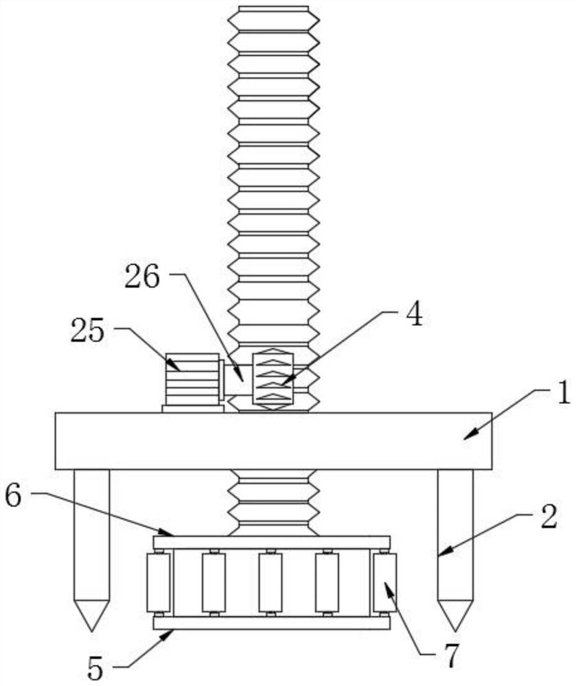
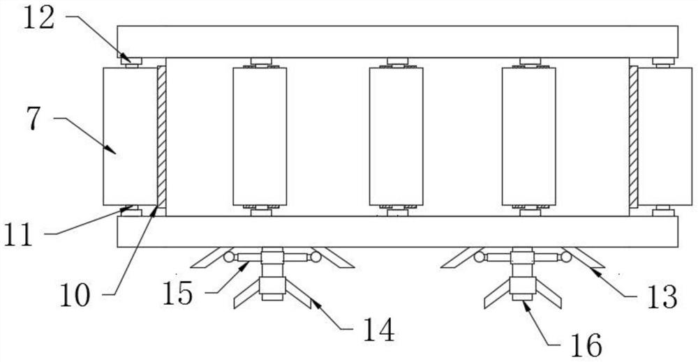
[0027] Such as Figure 1-5 As shown, the present invention provides a technical solution: an inspection well tamping device for engineering, including a base 1, a lifting worm 3, a driving gear 4, a tamping assembly, a first compacting mechanism, a second compacting mechanism and a crushing mechanism 9. The lifting worm 3 runs through the base 1 and is rotationally connected with the base 1. The driving gear 4 is located on the upper surface side of the base 1, and the driving gear 4 is meshed with the lifting worm 3. The tamping assembly is located on the base Below the seat 1 and fixedly connected with the lifting worm 3, the first compacting mechanism is located at the lower end of the compacting assembly, the second compacting mechanism is located at the side wall of the c...


PUM


Abstract

The invention discloses an inspection well tamping device for engineering, which comprises a base, a lifting worm, a driving gear, a tamping assembly, a first compacting mechanism, a second compacting mechanism and a crushing mechanism. The lifting worm runs through the base and is connected with the The base is rotationally connected, the drive gear is located on one side of the upper surface of the base, and the drive gear is meshed with the lifting worm, the tamping assembly is located below the base and is fixedly connected with the lifting worm, and the first compacting mechanism is located at the lower part of the component. In the present invention, a tamping assembly is arranged, and a first compacting mechanism is provided at the bottom of the tamping assembly, and a second compacting mechanism is provided on the side wall of the tamping assembly. When the tamping assembly rotates and moves down, it can Use the second compaction mechanism to compact the side wall of the inspection well. At the same time, when the tamping assembly is located at the bottom of the inspection well, the first compaction mechanism can be used to compact the bottom of the inspection well, so as to ensure good compaction effect and high compaction efficiency. Tall for ease of use.

Description

technical field [0001] The invention relates to the related technical field of inspection well construction, in particular to an engineering inspection well tamping device. Background technique [0002] The inspection well is set up for the maintenance of urban underground infrastructure such as power supply, water supply, drainage, sewage discharge, communication, cable TV, gas pipes, and street lamp lines, and is convenient for installation. It is generally installed at the intersection of pipelines, at the turning, at the change of pipe diameter or slope, and at a certain distance on the straight pipe section, which is convenient for regular inspection of auxiliary structures. The installed pit is compacted to ensure the stability of the inspection well installation. [0003] However, the existing inspection well tamping device has the following disadvantages: the side wall and the bottom of the inspection well installation pit cannot be tamped at the same time during th...

Claims


Application Information

Patent Timeline
Patent Type & Authority Patents(China)
IPC IPC(8): E02D3/046B02C18/10B08B1/02
CPCE02D3/046B02C18/10B08B1/02
Inventor 姚炜炜熊婧冯香君
Owner 盐城国睿信科技有限公司
Learn More