
Micro-scale charge detonation pressure and detonation velocity test system based on MEMS pressure-conducted probe

A test system and micro-scale technology, applied in ammunition tests, devices using electric/magnetic methods, ammunition, etc., can solve problems such as mutual interference, detonation velocity measurement error, large size, etc., to improve signal-to-noise ratio, improve The effect of measurement accuracy

Active Publication Date: 2020-03-27
XI AN JIAOTONG UNIV
View PDF7 Cites 5 Cited by
  • Summary
  • Abstract
  • Description
  • Claims
  • Application Information

AI Technical Summary

Problems solved by technology

However, the above methods have some problems in characterizing the output performance of micro-scale charges: first, two different test systems are required to measure the detonation pressure and detonation velocity, which will result in higher test costs; second, the size of the traditional electrical probe Larger and mutual interference will cause a certain detonation velocity measurement error; third, the traditional electrical probe method can only obtain the average detonation velocity between certain measurement points, but cannot obtain the detonation velocity growth curve

Method used


Image

  • Micro-scale charge detonation pressure and detonation velocity test system based on MEMS pressure-conducted probe
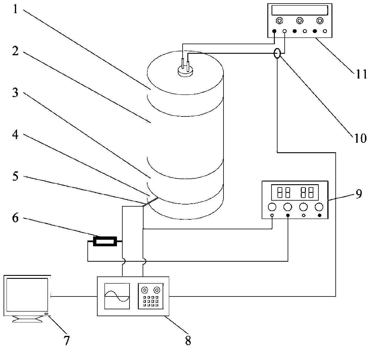
  • Micro-scale charge detonation pressure and detonation velocity test system based on MEMS pressure-conducted probe
  • Micro-scale charge detonation pressure and detonation velocity test system based on MEMS pressure-conducted probe

Examples


Embodiment Construction

[0021] The present invention will be described in detail below in conjunction with the accompanying drawings and embodiments.

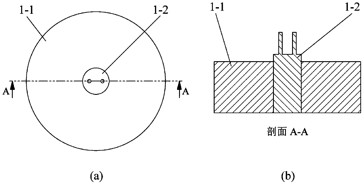
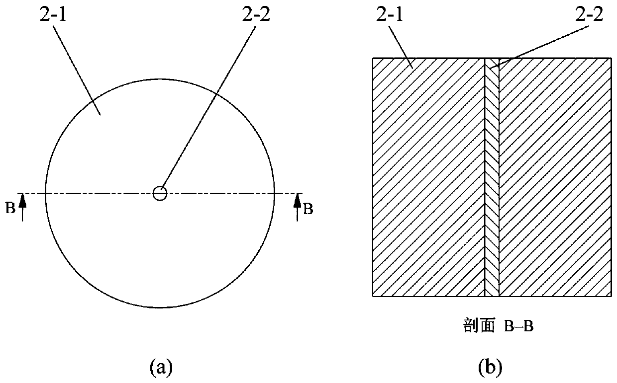
[0022] refer to figure 1 , figure 2 , image 3 , Figure 4 , Figure 5 , Image 6 with Figure 7 , a micro-scale charge detonation pressure and detonation velocity test system based on MEMS pressure conduction probes, comprising a detonating device 1, a detonator 1-2 fixed at the center of a detonator shell 1-1 of the detonating device 1 through a through-hole structure, and a detonator The lower end of the shell 1-1 is connected and fixed with the upper end of the charge shell 2-1 of the micro-scale charge body 2 through glue, and the center of the charge shell 2-1 is equipped with an explosive agent 2-2 through a micro-scale through-hole structure. The lower end of the charge shell 2-1 is connected and fixed by glue and the medium shell 3-1 of the inert medium 3, and the center of the medium shell 3-1 is fixed with a medium 3-2 through a thro...


PUM


Abstract

The invention relates to a micro-scale charge detonation pressure and detonation velocity test system based on a MEMS pressure-conducted probe. The system comprises an initiation device, wherein the lower end of the initiation device and the upper end of a micro-scale charge body are connected and fixed, the lower end of the micro-scale charge body is fixed to the upper end of an inert medium, andthe lower end of the inert medium is fixedly connected with a bottom plate; the edge of the micro-scale charge body and the inert medium is embedded with the MEMS pressure-conducted probe, and leadsof the MEMS pressure-conducted probes are led out from the interfaces of the inert medium and the bottom plate; the leads, a resistor and a constant voltage source of the MEMS pressure-conducted probeform a current loop; the leads of the MEMS pressure-conducted probe are connected with the input end of an oscilloscope; and the initiation device is connected with an initiator, the initiator is connected with the input end of the oscilloscope through a current ring, and the output end of the oscilloscope is connected with a computer. The MEMS pressure-conducted probe can obtain the explosive detonation velocity and the initial velocity of the medium shockwave at the same time, so that a detonation velocity growth curve and the end face output detonation pressure of the micro-scale charge are calculated and obtained. The system is suitable for measuring the output performance of micro-scale charge, and improves the measuring precision.

Description

technical field [0001] The invention belongs to the technical field of microscale charge detonation pressure and detonation velocity testing, in particular to a microscale charge detonation pressure and detonation velocity test system based on MEMS pressure guidance probes. Background technique [0002] With the continuous development of micro-sized pyrotechnic products, the output performance test of pyrotechnic agents at the micro scale has become a key problem to be solved urgently, among which the detonation pressure and detonation velocity are important parameters to characterize the output performance of pyrotechnic agents. Among the existing detonation pressure measurement methods, the impedance matching method is the most commonly used method. It indirectly measures the shock wave parameters in the adjacent medium and uses the principle of impedance matching to reverse detonation pressure. Among the existing detonation velocity measurement methods, the electric probe...

Claims


Application Information

Patent Timeline
Patent Type & Authority Applications(China)
IPC IPC(8): F42B35/00G01P3/42
CPCF42B35/00G01P3/42
Inventor 张国栋刘元赵玉龙韦学勇张一中王馨晨
Owner XI AN JIAOTONG UNIV
Learn More