Lifting hanger for pre-branched cable and method for lifting pre-branched cable

A technology of pre-branching and cables, which is applied in the field of lifting hangers for pre-branching cables and lifting of pre-branching cables, and can solve the problems of low reliability and safety

Pending Publication Date: 2020-03-13
高桥防火科技股份有限公司
View PDF0 Cites 2 Cited by
  • Summary
  • Abstract
  • Description
  • Claims
  • Application Information

AI Technical Summary

Problems solved by technology

[0004] The technical problem to be solved by the present invention is to provide a lifting hanger for pre-branched cables and a pre-branched cable in order to overcome the defects of lower reliability and safety of lifting in the prior art for pre-branched cables. Lifting method of branch cables

Method used


Image

  • Lifting hanger for pre-branched cable and method for lifting pre-branched cable
  • Lifting hanger for pre-branched cable and method for lifting pre-branched cable
  • Lifting hanger for pre-branched cable and method for lifting pre-branched cable

Examples


Embodiment 1

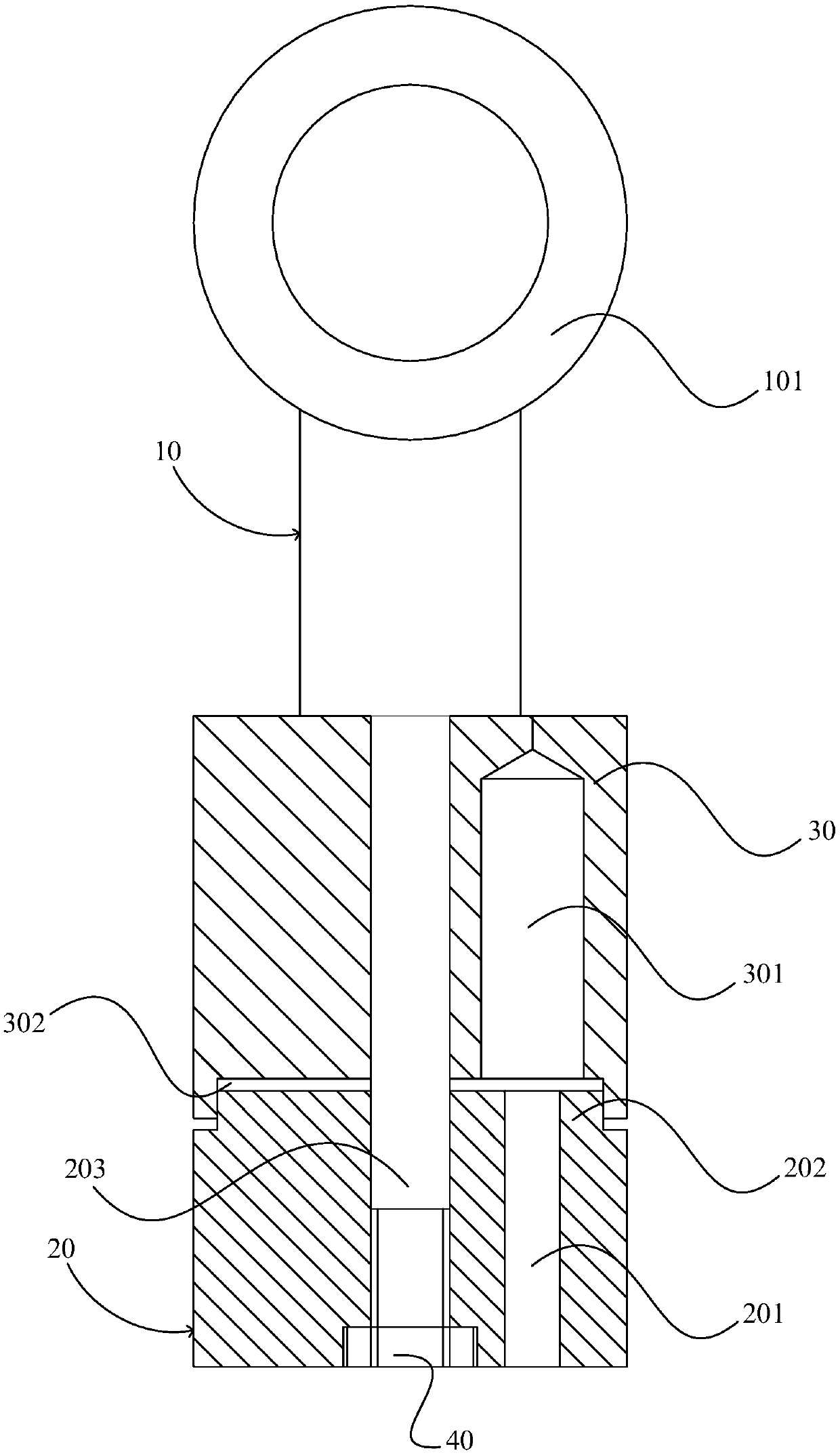
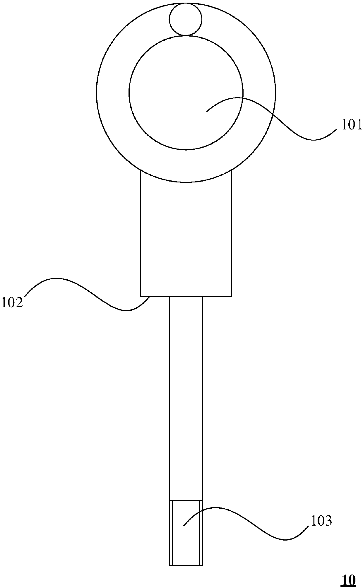
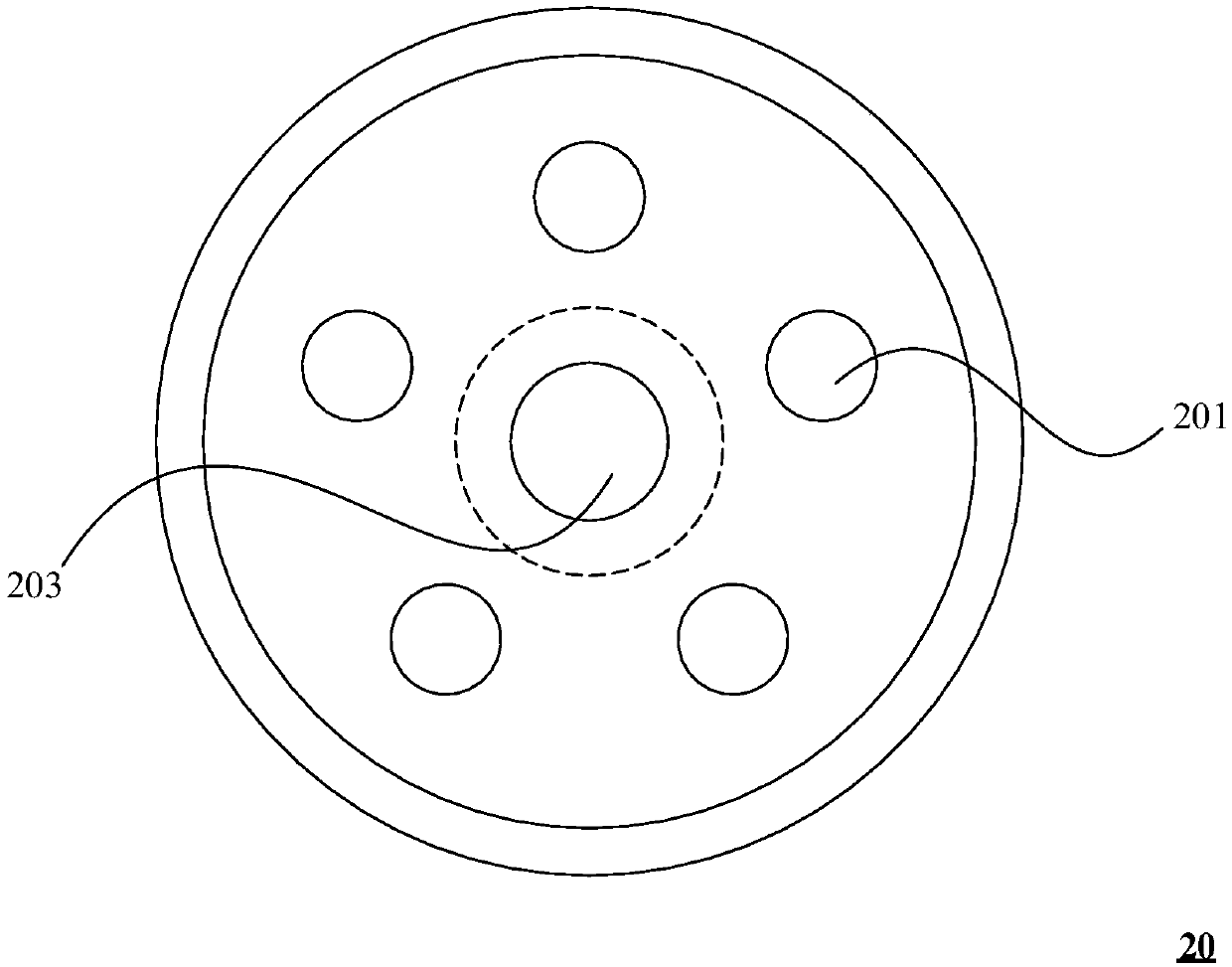
[0062]This embodiment discloses a lifting hanger for a pre-branched cable, the pre-branched cable has multiple wire cores, refer to Figure 1-4 It should be understood that the lifting hanger includes a boom 10 , a bearing block 20 and a plurality of limiting parts (not shown in the figure). The boom 10 has a head end and a tail end along the length direction, and the head end of the boom 10 has a lifting ear 101 . The load-bearing block 20 is sleeved on the tail end of the suspender 10, and the load-bearing block 20 is provided with a plurality of first accommodating holes 201 ( image 3 5 first accommodating holes 201 are shown in , and the first accommodating holes 201 extend along the length direction of the boom 10 . A plurality of stoppers abut against one end of the load-bearing block 20 toward the head end of the boom 10, and the plurality of stoppers are arranged in one-to-one correspondence with the plurality of first accommodating holes 201. The second accommodati...

Embodiment 2

[0073] This embodiment discloses a hoisting method for pre-branched cables. The hoisting method utilizes the hoisting hanger in Embodiment 1. Refer to Figure 5 It is to be understood that the hoisting method comprises the following steps:

[0074] Step 100, stripping off the end of the pre-branched cable, so that multiple wire cores are exposed to a preset length;

[0075] Step 200, make a plurality of wire cores pass through the load-bearing block through a plurality of first accommodating holes and expose to the load-bearing block;

[0076] Step 300, sleeve the plurality of washers on the plurality of wire cores respectively, so that the plurality of washers fit on the bearing block;

[0077] Step 400, connecting multiple limiters to multiple wire cores respectively;

[0078] Step 500, sleeve the gland on a plurality of position-limiting parts through a plurality of second accommodating holes, and connect the gland to the load-bearing block;

[0079] Step 600 , make the ...


PUM


Abstract

The invention provides a lifting hanger for a pre-branched cable and a method for lifting the pre-branched cable. The pre-branched cable is provided with multiple cable cores, the lifting hanger includes a suspender, a force-bearing block and a plurality of limit pieces, the suspender has a head end and a tail end in the length direction, and the head end of the suspender is provided with a lifting lug; the force-bearing block is arranged on the tail end of the suspender in a sleeving manner, the force-bearing block is provided with a plurality of first containing holes for a plurality of cable cores to pass through, and the first containing holes are arranged at intervals; and the multiple limit pieces abut against the end, facing the head end of the suspender, of the force-bearing block,the multiple limit pieces are arranged in correspondence with the multiple first containing holes in a one-to-one manner, second containing holes for the cable cores to pass through are formed in thelimit pieces, the size of the cross sections of the limit pieces in the radial direction of the first containing holes is larger than the diameter of the first containing holes, and the limit piece is used for being connected to the parts, extending out of the force-bearing block, of the cable cores. Even if the pre-branched cable is heavy, the limit pieces cannot pass through the first containing holes, and the lifting hanger has high lifting reliability and safety.

Description

technical field [0001] The invention relates to a lifting hanger for pre-branch cables and a hoisting method for pre-branch cables. Background technique [0002] The application of pre-branch cables is becoming wider and wider, from the most conventional plastic cables to today's mineral cables, the application of pre-branches is quite large. However, the lifting hanger of the pre-branch cable has always used a stainless steel mesh cover with hanging ears. When lifting the pre-branch cable, it is necessary to directly put the mesh cover on the end of the cable, and then use the hoop to Hold the net cover tightly on the cable, and finally lift it through the hanging lug. This kind of operation seems to be simple and convenient, but in fact there are great hidden dangers. It mainly relies on the friction between the cable and the net cover to lift and install the cable. Once the weight of the cable is heavy or the hoop is loose, etc., Then it will make the friction between t...

Claims


Application Information

Patent Timeline
Patent Type & Authority Applications(China)
IPC IPC(8): B66C1/10H02G15/076
CPCB66C1/10H02G15/076
Inventor 张国宾王建中支银林钱云云
Owner 高桥防火科技股份有限公司
Why Eureka
Try Eureka