


Quick Research
Generate reliable direction feasibility study reports for your R&D in just a few steps.

Technical Q&A
Discover and master advanced knowledge NOW. Basics, ideas, possibilities, all at once.

Find Solutions
As an expert in R&D theories, this can generate solutions to your technical problems instantly.

Evaluate Feasibility
Analyze your overall solution with one click, know your potential R&D risks in advance.

Monitor Landscape
Get weekly tech updates, stay abreast of the latest tech innovations and key insights.
An automatic control teaching demonstration device
A demonstration device and drive disk technology, applied in projection devices, optics, educational appliances, etc., can solve the problems that cannot meet the viewing requirements of different teachers, the size of the screen cloth cannot be adjusted, and the projection area can be adjusted to facilitate display Angle, easy to adjust, easy to use effect
- Summary
- Abstract
- Description
- Claims
- Application Information
AI Technical Summary
Problems solved by technology
Method used
Image

Examples
Embodiment 1
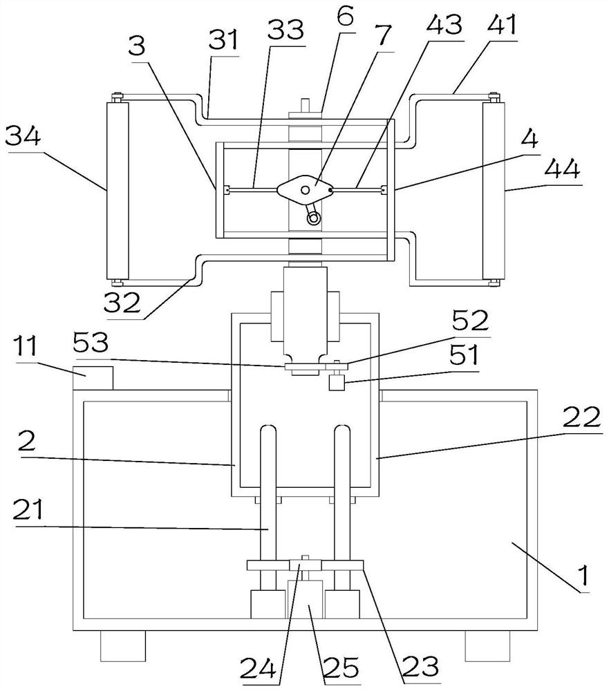
[0023] see Figure 1~3 , in Embodiment 1 of the present invention, an automatic control teaching demonstration device includes a base 1, a lifting assembly 2 installed on the base 1, a support member 6 rotatably arranged on the lifting assembly 2, and a support member 6 arranged on the support member 6. The left extension assembly 3 and the right extension assembly 4, the left extension assembly 3 includes a frame one 31 and a connecting rod one 33, the right extension assembly 4 includes a frame two 41 and a connecting rod two 43, and the frame one 31 and frame 2 41 are respectively slid through through hole 1 62 and through hole 2 63 on the support member 6, and the frame 1 31 and frame 2 41 are respectively provided with reel 1 34 and Reel 2 44, and reel 1 34 and reel 2 44 are all curled with interconnected projection screens, and the first rotating assembly 7 is installed on the mounting groove 64 inside the support member 6, and the first rotating assembly 7 is set. It i...
Embodiment 2
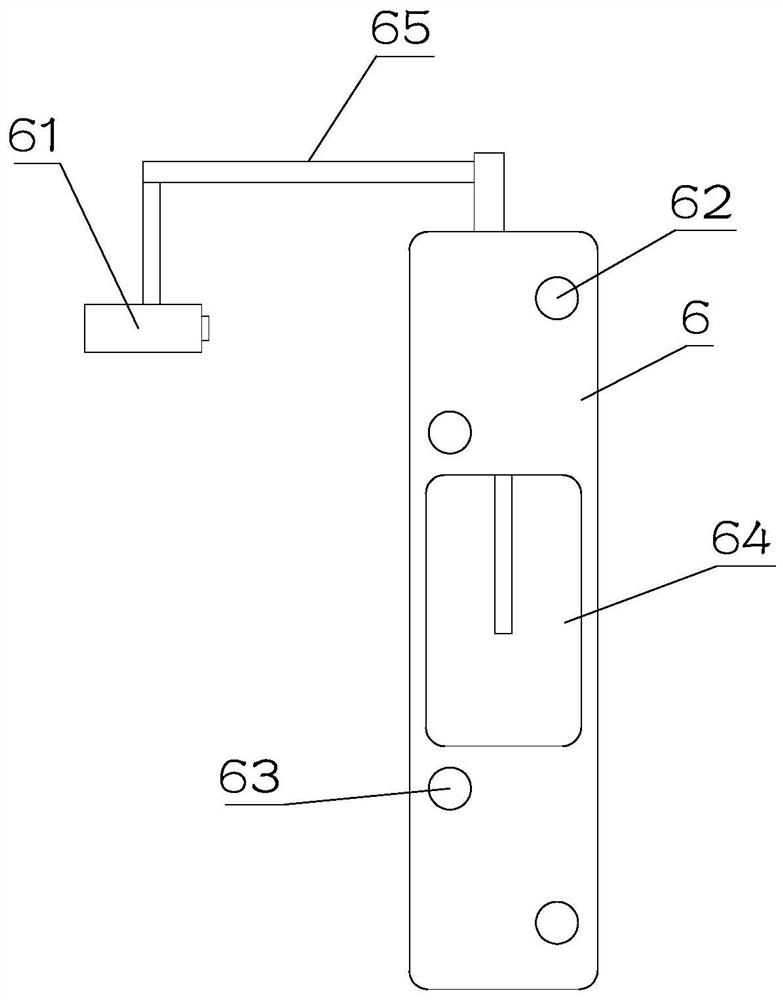
[0026] see Figure 1~3 The main difference between this embodiment 2 and embodiment 1 is that a pole 65 is fixedly installed on the support member 6, and a projector 61 is installed on the end of the pole 65 away from the support member 6, and the projector 61 is set for Projection on the projection screen.
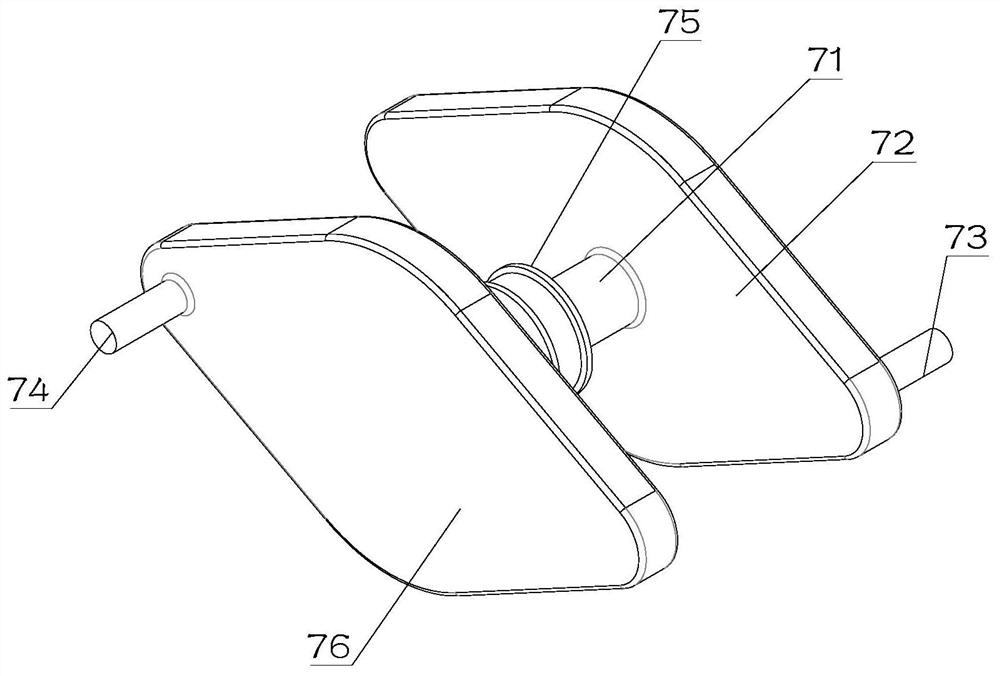
[0027] A motor three is also arranged inside the installation slot 64 , and the motor three is in transmission connection with the pulley 75 on the rotating shaft 71 . The third motor provides power for the rotation of the rotating shaft 71 .
[0028] The bottom of the support member 6 is rotatably installed on the lifting assembly 2, which is convenient for adjusting the angle of the support member 6, thereby adjusting the angle of the projection screen.
[0029] The lifting assembly 2 is provided with a second rotating assembly that drives the support member 6 to rotate automatically. The second rotating assembly provides power for the rotation of the support member ...
PUM
 Abstract
Description
Claims
Application Information
 - R&D Engineer
- R&D Manager
- IP Professional
- Industry Leading Data Capabilities
- Powerful AI technology
- Patent DNA Extraction
Browse by: Latest US Patents, China's latest patents, Technical Efficacy Thesaurus, Application Domain, Technology Topic, Popular Technical Reports.
© 2024 PatSnap. All rights reserved.Legal|Privacy policy|Modern Slavery Act Transparency Statement|Sitemap|About US| Contact US: help@patsnap.com