Filter tank

A filter tank and filter screen technology, applied in the field of filter tanks, can solve problems such as affecting production efficiency, consuming manpower, and easily blocking the filter screen, reducing labor costs, reducing the number of times of replacing the filter screen, and avoiding work stoppage.

Pending Publication Date: 2020-02-07
广东长石环保科技有限公司
View PDF0 Cites 1 Cited by
  • Summary
  • Abstract
  • Description
  • Claims
  • Application Information

AI Technical Summary

Problems solved by technology

[0002] At present, most processing enterprises will inevitably produce waste water in the process of processing and production. The waste water is mixed with liquid and solid. In order to prevent the waste water from polluting the environment, it is essential to filter and separate the waste water. The conventional method The filter is used for filtration and separation, but the disadvantage is that the filter is easy to block, and the filter needs to be replaced frequently manually, which not only consumes a lot of manpower, but also requires shutdown processing, which affects production efficiency

Method used


Image

  • Filter tank
  • Filter tank
  • Filter tank

Examples


Embodiment 1

[0024] Such as figure 1 as shown, figure 1 It is the structural diagram of filter tank in the embodiment. The filter tank of the present invention includes a tank body 1 and a filter core 2, the filter core 2 is located in the tank body 1, and the filter core 2 is arranged between the discharge end 11 and the discharge end 12 of the tank body 1; the filter core 2 comprises a filter screen 21 And the solid-liquid separator 22, the filter screen 21 is wrapped in the solid-liquid separator 22. Wherein, the waste water enters from the discharge end 11 of the tank body 1 , undergoes solid-liquid separation through the filter screen 21 and the solid-liquid separator 22 , and finally discharges the solid and liquid from the discharge end 12 of the tank body 1 .

[0025] The discharge end 12 of the tank body 1 includes a solid discharge port 121 and a liquid discharge port 122, the solid discharge port 121 communicates with the area where the solid-liquid separator 22 is located, an...

Embodiment 2

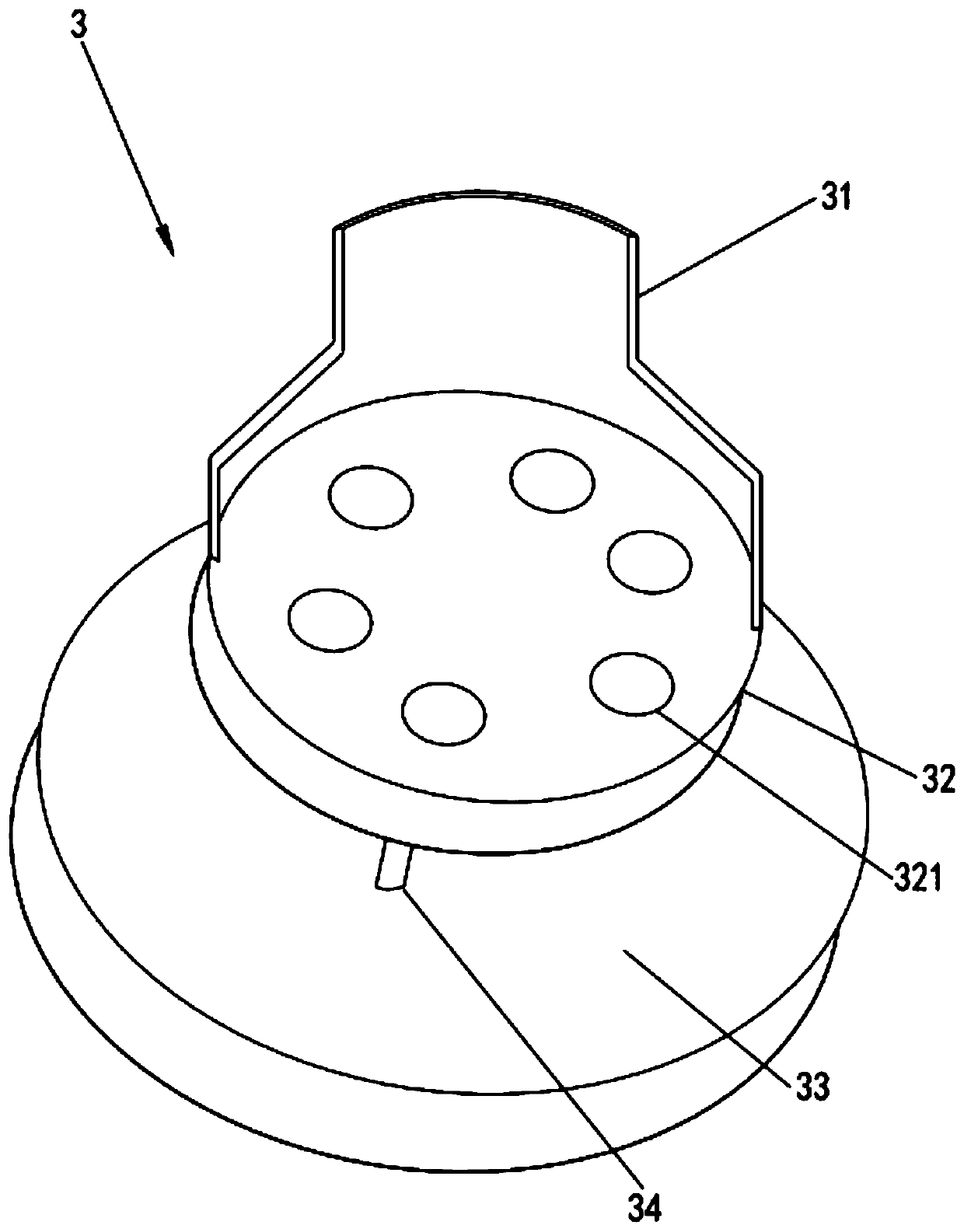
[0037] The difference between this embodiment and Embodiment 1 is that, if image 3 as shown, image 3 It is a structural diagram of the water separator 3 in the embodiment. The filter tank also includes a water separator 3 located between the discharge end 11 and the separation disc body 221 . The water separator 3 includes a water diversion cover 31, a first water diversion plate 32, a second water diversion plate 33 and a water diversion connector 34. The water diversion cover 31 is connected to the discharge end 11, and the water diversion cover 31 is covered with a On the first water distribution board 32 , the second water distribution board 33 is connected to the first water distribution board 32 through the water distribution connection part 34 . Specifically, the water separating cover 31 is funnel-shaped.

[0038] Preferably, the first water diversion plate 32 is provided with a plurality of water diversion holes 321, and the plurality of water diversion holes 321...


PUM

PropertyMeasurementUnit
thicknessaaaaaaaaaa
thicknessaaaaaaaaaa
thicknessaaaaaaaaaa

Abstract

The invention discloses a filter tank which comprises a tank body and a filter element, and the filter element is arranged in the tank body; the filter element comprises a filter screen and a solid-liquid separator, and the filter screen wraps the solid-liquid separator. Liquid and solids in wastewater can be effectively separated through the solid-liquid separator; meanwhile, the separated liquidis filtered and drained through the filter screen; the solid-liquid separator is arranged outside the filter screen, so that solids in the wastewater are blocked outside the filter screen and are discharged along the solid-liquid separator in the washing process, the phenomenon that the solids block the filter screen is effectively prevented, the frequency of replacing the filter screen is reduced, the labor cost is further reduced, and meanwhile, the situation of shutdown treatment due to blockage of the filter screen can be avoided.

Description

technical field [0001] The invention relates to the technical field of filter equipment, in particular to a filter tank. Background technique [0002] At present, most processing enterprises will inevitably produce waste water in the process of processing and production. The waste water is mixed with liquid and solid. In order to prevent the waste water from polluting the environment, it is essential to filter and separate the waste water. The conventional method It is to filter and separate through the filter, but the disadvantage is that the filter is easy to block, and the filter needs to be replaced frequently manually, which not only consumes a lot of manpower, but also needs to be shut down, which affects the production efficiency. Contents of the invention [0003] Aiming at the deficiencies of the prior art, the invention provides a filter tank. [0004] A filter tank disclosed by the invention comprises a tank body and a filter core, the filter core is arranged o...

Claims


Application Information

Patent Timeline
Patent Type & Authority Applications(China)
IPC IPC(8): B01D29/35B01D29/66B01D29/58
CPCB01D29/35B01D29/58B01D29/66
Inventor 陈月粦
Owner 广东长石环保科技有限公司
Why Eureka
Try Eureka