
Inflation-free tire

A technology for non-pneumatic tires and tires, applied to non-pneumatic tires, tire parts, wheels, etc., can solve problems such as poor tire comfort, insufficient tire support, etc., and achieve the effect of ensuring durability

Pending Publication Date: 2020-02-04
CHENG SHIN RUBBER XIAMEN IND
View PDF0 Cites 0 Cited by
  • Summary
  • Abstract
  • Description
  • Claims
  • Application Information

AI Technical Summary

Problems solved by technology

[0003] In order to pursue the safety of vehicles, the existing portable electric recreational vehicles are often equipped with full solid non-inflatable tires, which can avoid the safety hazards caused by unexpected problems such as tire blowouts to a certain extent, but the cushioning and shock absorption effect of solid tires is not good. The tire jumps a lot when driving, resulting in poor driving comfort
like figure 1 As shown, in order to avoid the problem of poor comfort, a plurality of circumferential holes 1' or axial holes 2' are designed inside the solid tire in the existing market to reduce the weight of the tire, but it cannot completely improve the comfort of the tire. At the same time, the support of the tire is insufficient when driving, and it is easy to collapse and cause the problem of poor tire durability.
At the same time, the heat dissipation of solid tires is not good, and it is easy to generate heat during driving, which will lead to the phenomenon of melting and destroying the inside of solid tires, which will eventually affect the durability of tires.
[0004] Therefore, general air-free tires cannot meet the comfort and durability requirements of the vehicle when it is installed on a portable electric recreational vehicle.

Method used


Image

  • Inflation-free tire
  • Inflation-free tire
  • Inflation-free tire

Examples


Embodiment Construction

[0024] In order to further explain the technical solution of the present invention, the present invention will be described in detail below through specific examples.

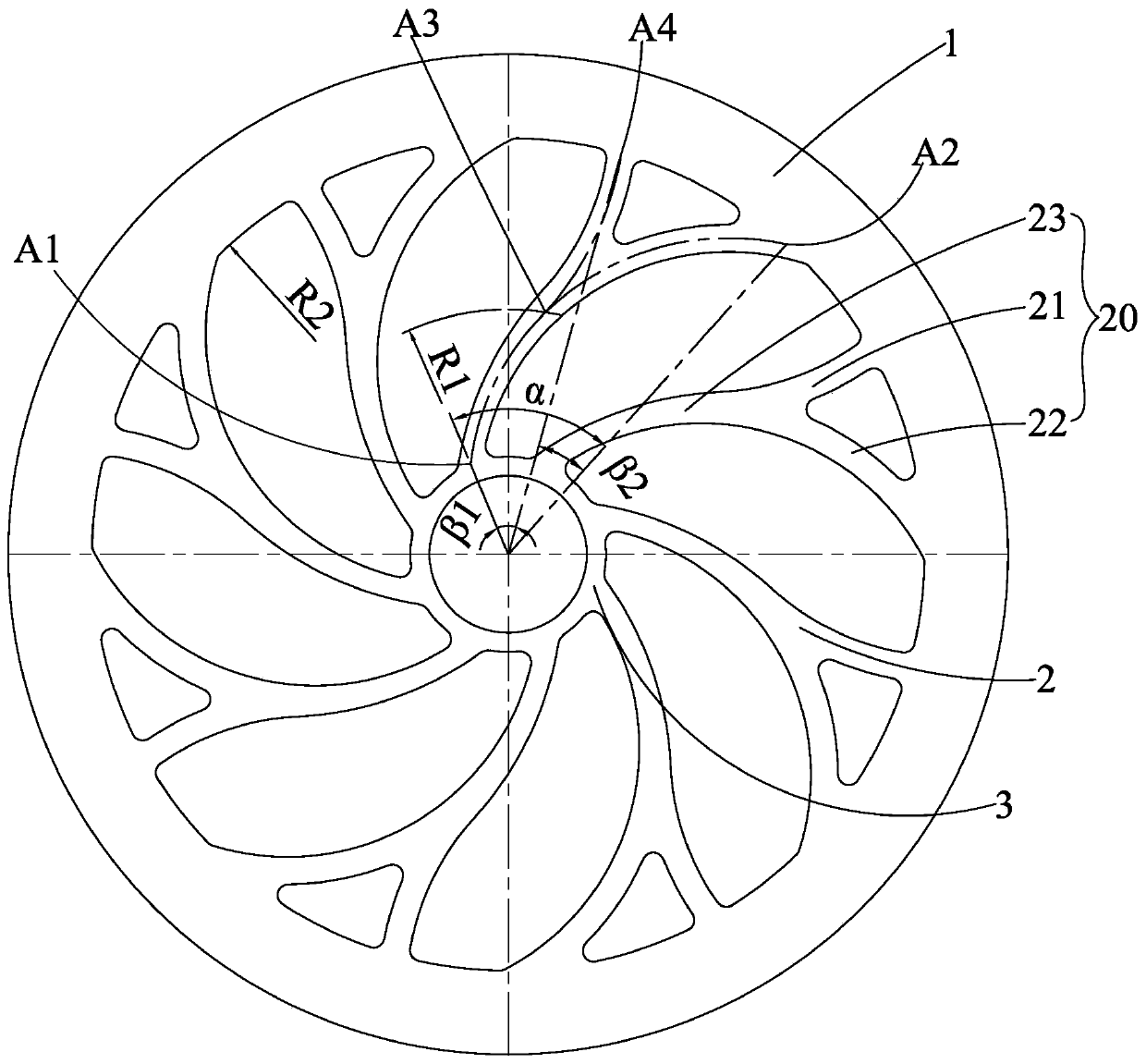
[0025] Such as Figure 2 to Figure 7 As shown, the present invention mainly discloses a structural design of an air-free tire for a portable electric recreational vehicle, figure 2 The vertical direction is set as the tire radial direction, the radial direction close to the tire rotation axis is the radial inner side, the radial direction away from the tire rotational axis is the radial outer side, the vertical direction is set as the tire circumferential direction, and the lateral direction is set as the tire axial direction.

[0026] The tire includes a tread portion 1, a support portion 2, and a tire bottom 3. The support portion 2 of the tire includes a plurality of Y-shaped main support frames 20 and strip-shaped sub-support frames 40, and the strip-shaped sub-support frames 40 are located at two circumfe...


PUM


Abstract

The invention discloses an inflation-free tire. The inflation-free tire comprises a tire face part, a supporting part and a tire bottom part. The supporting part of the tire comprises multiple Y-shaped main supporting frames and strip-shaped auxiliary supporting frames. Each strip-shaped auxiliary supporting frame is located between the two corresponding Y-shaped main supporting frames in the circumferential direction. Each Y-shaped main supporting frame is composed of a left rod, a right rod and a lower rod. The left rod and the right rod on each same Y-shaped main supporting frame are not symmetrical to each other. The edges of the two sides of each left rod and the edges of the two sides of each right rod are bent towards the inner portions of the Y shapes. The bent-in direction of thelower rods is the same as that of the right rods. The edges of the two sides of each left rod, the edges of the two sides of each right rod and the edges of the two sides of each lower rod are bent inin a linear or arc-shaped manner. Each strip-shaped auxiliary supporting frame is composed of an upper auxiliary supporting frame body and a lower auxiliary supporting frame body. During running of the tire, the Y-shaped main supporting frames and the strip-shaped auxiliary supporting frames can provide enough supporting and appropriate deformation, and it is ensured that the comfortable capacityis improved while running durability of the tire is ensured.

Description

technical field [0001] The invention relates to the technical field of tires, in particular to an air-free tire structure for recreational vehicles. Background technique [0002] In recent years, the domestic recreational vehicle market has developed rapidly, especially the portable electric recreational vehicle has been vigorously developed. Portable electric recreational vehicles are favored by young consumers because of their simple structure, brisk driving, and strong entertainment, and have gradually become a new entertainment transportation tool. Because the cushioning and shock absorption structure of portable electric recreational vehicles is relatively simple, the cushioning effect of tires will directly affect the overall use feeling of the vehicle, and consumers pay attention to the cushioning comfort of tires. In addition, because the safety protection structure of portable electric recreational vehicles is relatively simple, consumers pay more attention to the ...

Claims


Application Information

Patent Timeline
IPC IPC(8): B60C7/00B60B9/00
CPCB60C7/00B60B9/00
Inventor 许美蕊
Owner CHENG SHIN RUBBER XIAMEN IND
Learn More