


Quick Research
Generate reliable direction feasibility study reports for your R&D in just a few steps.

Technical Q&A
Discover and master advanced knowledge NOW. Basics, ideas, possibilities, all at once.

Find Solutions
As an expert in R&D theories, this can generate solutions to your technical problems instantly.

Evaluate Feasibility
Analyze your overall solution with one click, know your potential R&D risks in advance.

Monitor Landscape
Get weekly tech updates, stay abreast of the latest tech innovations and key insights.
An adjustable resistor terminal pin cutting device for computer production
A cut-off device and adjustable technology, applied in the direction of filter screen, grid, solid separation, etc., can solve the problems of long processing time, inaccurate positioning, damaged resistance, etc.
- Summary
- Abstract
- Description
- Claims
- Application Information
AI Technical Summary
Problems solved by technology
Method used
Image

Examples
Embodiment 1
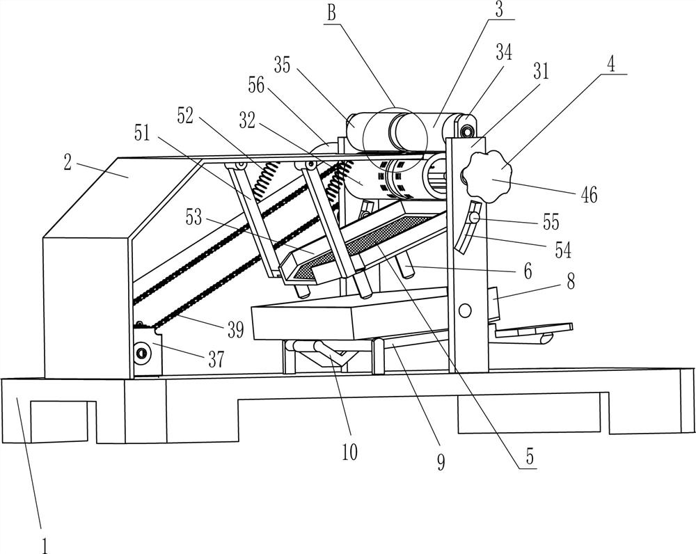
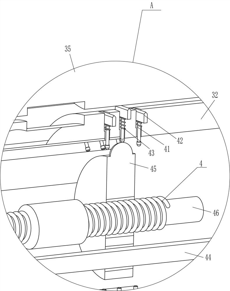
[0023] A device for cutting off pins at both ends of an adjustable resistor for computer production, such as Figure 1-6 As shown, it includes a base 1, a frame 2, a feeding device 3 and an adjustable cutting device 4. The left side of the base 1 is equipped with a frame 2, and the right side of the base 1 is provided with a feeding device 3. The feeding device 3 is used for conveying needs. For the resistance components to be processed, the feeding part of the feeding device 3 is provided with an adjustable cutting device 4, and the adjustable cutting device 4 is used to adjust the length of the lead after the resistance is cut.
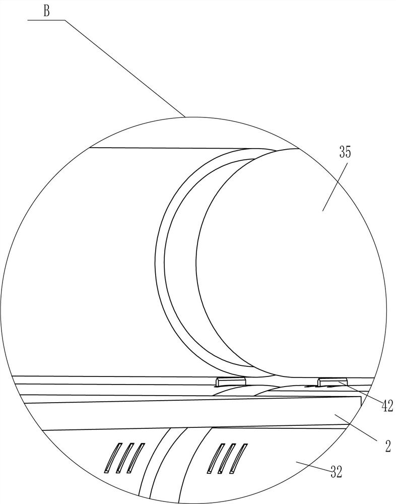
[0024] The feeding device 3 includes a vertical plate 31, a hollow roller 32, a slide plate 34, a solid roller 35, a first spring 36, a reduction motor 37, a sprocket wheel 38 and a chain 39; A vertical plate 31 is installed, and a hollow roller 32 is arranged in a rotating manner between the two vertical plates 31. The front side of the hollow roll...
Embodiment 2
[0028] On the basis of Example 1, such as figure 1 , 2Shown in and 6, it also includes a material shaking device 5, the material shaking device 5 includes a swing bar 51, a third spring 52, a screen frame 53, a rolling shaft 55 and a double-headed cam 56, and the top, front, and rear sides of the frame 2 are A swing rod 51 is installed in a rotating manner. A third spring 52 is connected between the upper part of the swing rod 51 and the inner top of the frame 2. A screen frame 53 is fixedly installed at the lower end of the swing rod 51. An arc is opened in the middle of the vertical plate 31. Shaped groove 54, this screen frame 53 right front and rear sides are all provided with rolling shaft 55, and this rolling shaft 55 cooperates with this arc groove 54, and this hollow roller 32 rear end is equipped with double-headed cam 56, and this double-headed cam 56 is in contact with the rolling shaft 55 at the rear.
[0029] When the resistor pins are cut off, many fine metal p...
Embodiment 3
[0031] On the basis of Example 2, such as figure 1 , 2 Shown in and 6, also comprise hollow cylinder 6 and steel ball 7, be fixedly connected with hollow cylinder 6 on this screen frame 53, steel ball 7 is placed in this hollow cylinder 6.
[0032] It also includes a material storage frame 8, a magnetic plate 9 and a special-shaped push rod 10, and a material storage frame 8 is arranged between the vertical plates 31 in a rotating manner, and the material storage frame 8 is located below the screen frame 53. On the base 1 A magnetic plate 9 is provided in a rotating manner, and the magnetic plate 9 is located below the material storage frame 8. A special-shaped ejector pin 10 is installed on the left part of the magnetic plate 9, and the special-shaped ejector pin 10 is in contact with the left bottom of the material storage frame 8. Cooperate.
[0033] When the screen frame 53 is swinging, it can drive the hollow cylinder 6 to continuously swing, so that the steel balls 7 i...
PUM
 Abstract
Description
Claims
Application Information
 - R&D Engineer
- R&D Manager
- IP Professional
- Industry Leading Data Capabilities
- Powerful AI technology
- Patent DNA Extraction
Browse by: Latest US Patents, China's latest patents, Technical Efficacy Thesaurus, Application Domain, Technology Topic, Popular Technical Reports.
© 2024 PatSnap. All rights reserved.Legal|Privacy policy|Modern Slavery Act Transparency Statement|Sitemap|About US| Contact US: help@patsnap.com