


Quick Research
Generate reliable direction feasibility study reports for your R&D in just a few steps.

Technical Q&A
Discover and master advanced knowledge NOW. Basics, ideas, possibilities, all at once.

Find Solutions
As an expert in R&D theories, this can generate solutions to your technical problems instantly.

Evaluate Feasibility
Analyze your overall solution with one click, know your potential R&D risks in advance.

Monitor Landscape
Get weekly tech updates, stay abreast of the latest tech innovations and key insights.
Blended wing body aircraft
A wing-body fusion and aircraft technology, applied in the field of wing-body fusion aircraft, can solve problems such as reducing aircraft lift
- Summary
- Abstract
- Description
- Claims
- Application Information
AI Technical Summary
Problems solved by technology
Method used
Image

Examples
Embodiment Construction
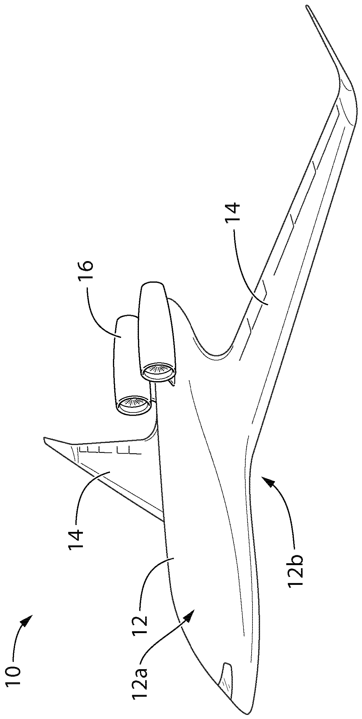
[0031] Blended wing-body aircraft designs are sometimes referred to as "wing-body hybrid" aircraft designs. In this specification (including the claims), it is to be understood that the term "fused wing body" encompasses aircraft designs sometimes referred to as "blended wing body" aircraft designs or "non-interrupted chord" aircraft designs. A non-interrupted chord aircraft is an aircraft in which the change in chord length of multiple span-wise sections is substantially smooth spanwise from the plane of symmetry of the wing to the wing tip. Such aircraft are also characterized by a smooth change in thickness of the spanwise section from the plane of symmetry of the wing to the wingtip.
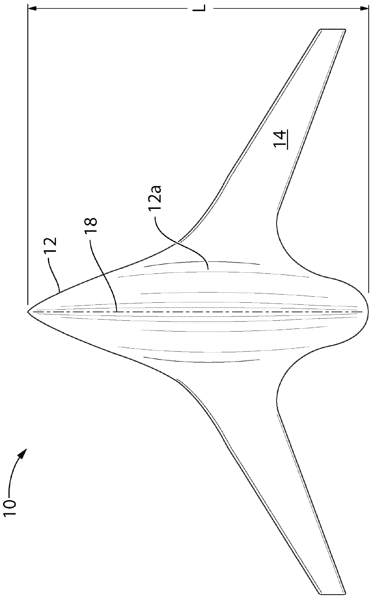
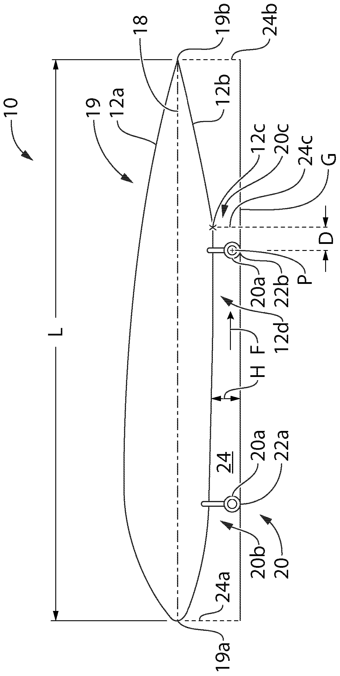
[0032] With reference to the accompanying drawings, and in particular to figure 1 , an exemplary blended wing body aircraft is shown at 10 . Aircraft 10 has a central fuselage 12 that may have lift generating properties. The center fuselage 12 has a front end and an opposite rear end. Ce...
PUM
 Abstract
Description
Claims
Application Information
 - R&D Engineer
- R&D Manager
- IP Professional
- Industry Leading Data Capabilities
- Powerful AI technology
- Patent DNA Extraction
Browse by: Latest US Patents, China's latest patents, Technical Efficacy Thesaurus, Application Domain, Technology Topic, Popular Technical Reports.
© 2024 PatSnap. All rights reserved.Legal|Privacy policy|Modern Slavery Act Transparency Statement|Sitemap|About US| Contact US: help@patsnap.com