Iron wire fixing plier for reinforcing steel and using method of iron wire fixing plier

A technology for fixing pliers and iron wires, which is applied in construction, building structure, and processing of building materials, etc. It can solve the problems of easy wrist strain and physical and mental inconvenience of workers, and achieve the effect of reducing physical and mental injuries and reducing labor intensity of workers.

Pending Publication Date: 2019-12-20
浙江中正岩土技术有限公司
View PDF0 Cites 1 Cited by
  • Summary
  • Abstract
  • Description
  • Claims
  • Application Information

AI Technical Summary

Problems solved by technology

[0002] In the construction of buildings, steel bars must be wound and fixed with iron wires. All building steel bar structures must implement this operation. The general practice in the market is to clamp the iron wires with a vise after passing around the crossed steel bars. Rotate, rotate at least three times before it can be fixed. Hundreds of thousands of steel wires need to be fixed in a day, and each time you need to rotate more than three times, it is a lot of challenges to the labor intensity and efficiency of labor. For a long time, Workers' wrists are prone to strain, causing a lot of inconvenience to workers' physical and mental health

Method used


Image

  • Iron wire fixing plier for reinforcing steel and using method of iron wire fixing plier
  • Iron wire fixing plier for reinforcing steel and using method of iron wire fixing plier
  • Iron wire fixing plier for reinforcing steel and using method of iron wire fixing plier

Examples


Embodiment Construction

[0025] The preferred embodiments of the present invention will be described in detail below in conjunction with the accompanying drawings, so that the advantages and features of the present invention can be more easily understood by those skilled in the art, so as to define the protection scope of the present invention more clearly.

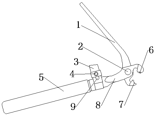
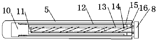
[0026] refer to Figure 1 to Figure 8 Shown, a kind of reinforced iron wire fixing pliers comprises a first locking clip 1, a second locking clip 8 and a shaft 2, and the shaft 2 runs through the first locking clip 1 and the second locking clip 8 so that the first locking clip 1. The second locking clip 8 is relatively rotatably connected, and the end of the second locking clip 8 is fixed with a fixed rod 13, and the outer circumference of the fixed rod 13 is provided with a circle of spiral notches 14, and the inside of the fixed rod 13 is a hollow structure , and its interior is prevented from being provided with a movable rod 11 that can be st...


PUM


Abstract

The invention discloses an iron wire fixing plier for reinforcing steel. The fixing plier is capable of quickly winding iron wires for binding, the efficiency is three times or above that of an original method, the labor intensity of workers is effectively reduced, and the physical and mental injuries to the workers in building operation are reduced. The fixing plier comprises a first locking clamp, a second locking clamp and a shaft, wherein the shaft penetrates through the first locking clamp and the second locking clamp; a fixing rod is fixed at the end part of one side of the second locking clamp, and a circular spiral notch is arranged on the outer circumference of the fixing rod; the fixing rod is of a hollow structure, a movable rod capable of stretching out or drawing back leftwards and rightwards is arranged in the fixing rod, and a fixing sleeve is fixed on the left side of the movable rod; a sleeve is in threaded connection with the left side of the fixing sleeve, and the right side end of the fixing sleeve extends to the right side end of the inner side of the sleeve and defines a movable bin with the right side end of the sleeve; a limiting ring is arranged in the movable bin and at the outer circumference of the fixing rod in a sleeving mode, and the right side end of the limiting ring is buckled and locked with the left side end of the sleeve; and the inner wallof the limiting ring is further provided with a guide, and the guide is embedded in the spiral notch on the outer circumference of the fixing rod.

Description

technical field [0001] The invention belongs to the field of building construction, in particular to a steel bar iron wire fixing pliers. Background technique [0002] In the construction of buildings, steel bars must be wound and fixed with iron wires. All building steel bar structures must implement this operation. The general practice in the market is to clamp the iron wires with a vise after passing around the crossed steel bars. Rotate, rotate at least three times before it can be fixed. Hundreds of thousands of steel wires need to be fixed in a day, and each time you need to rotate more than three times, it is a lot of challenges to the labor intensity and efficiency of labor. For a long time, Workers' wrists are prone to strain, which causes a lot of inconvenience to workers' physical and mental health. Contents of the invention [0003] The technical problem to be solved by the present invention is to provide a steel bar wire fixing pliers, which can quickly wrap ...

Claims


Application Information

Patent Timeline
Patent Type & Authority Applications(China)
IPC IPC(8): E04G21/12
CPCE04G21/123
Inventor 周旭东陈美娟李泽良周嵩
Owner 浙江中正岩土技术有限公司
Why Eureka
Try Eureka