
Tripod capable of being quickly retracted and expanded

A tripod, fast technology, applied in the direction of the machine/stand, rod connection, connecting components, etc., can solve the problem that the tripod cannot be retracted quickly, and achieve the effect of rapid retraction and simplified retraction operation

Pending Publication Date: 2019-12-13
张磊
View PDF0 Cites 7 Cited by
  • Summary
  • Abstract
  • Description
  • Claims
  • Application Information

AI Technical Summary

Problems solved by technology

[0006] In order to solve the problem that the existing tripod cannot be quickly retracted, the present invention provides a fast retractable tripod, which can realize the synchronous locking of all joints by making one action on the handle, and realize the synchronous unlocking of all joints by performing another action

Method used


Image

  • Tripod capable of being quickly retracted and expanded
  • Tripod capable of being quickly retracted and expanded
  • Tripod capable of being quickly retracted and expanded

Examples


Embodiment 1

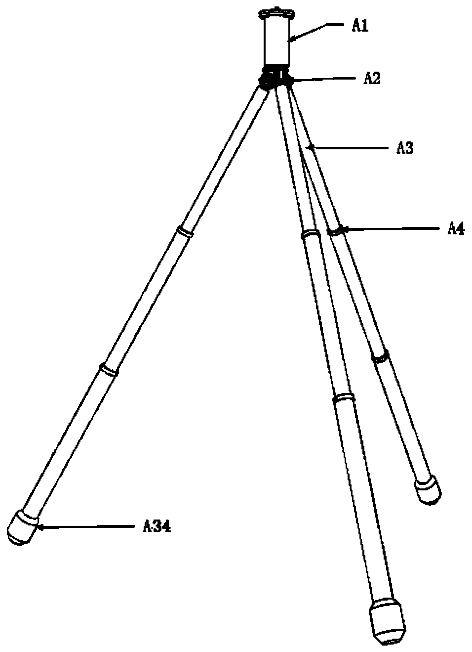
[0092] figure 1 As shown, the tripod consists of four parts: handle A1, bracket A2, outrigger A3 (3 branches, each with 3 sections), and A4 joints (each outrigger has 2 joints, 6 in total).

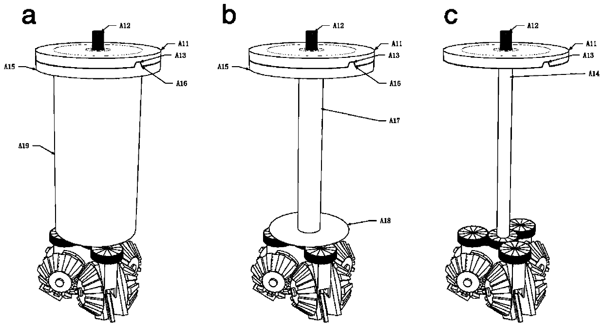
[0093] figure 2 The handle is shown with the tripod joint locked. The operating mechanism of the handle includes a pan-tilt bearing plate, an outer shaft A17, a handle chassis A18, a handle shell A19, a handle upper cover A15 and an inner shaft A14; the upper end of the inner shaft A14 is connected with the pan-tilt bearing plate, and the The outer shaft A17 is sleeved outside the inner shaft A14, the two ends of the outer shaft A17 are respectively connected to the handle chassis A18 and the handle upper cover A15, and the two ends of the handle shell A19 are respectively connected to the handle chassis A18 and the handle upper cover A15; the handle shell The rotation of A19 drives the handle chassis A18 to rotate and then drives the twisting mechanism to rotate. figure 2 where a is...

Embodiment 2

[0102] Figure 8 As shown, the tripod consists of four parts: handle B1, bracket B2, outrigger B3, and joint B4.

[0103] Figure 9 The handle is shown with the tripod joint locked. The operating mechanism of the handle includes a pan-tilt bearing plate B101, a spring leaf B106, a handle shell B104 and a handle bottom shell B105. The bottom end is hinged, the upper end of the handle is hinged to the handle extension rod B109, the handle extension rod B109 is hinged to the longitudinal axis of the handle extension rod B110, and the handle push rod B111 is hinged; the handle push rod B111 is carried by the pan / tilt The gap of disc B103 penetrates into the interior of the pan / tilt bearing disc. There are two nested concentric shafts inside the handle. The inner shaft B118 is fixedly connected to the center of the support B21. The outer shaft sleeve B117 is outside the inner shaft; the top of the outer shaft is fixedly connected to two The same support column B116, the support ...

Embodiment 3

[0114] Figure 17 As shown, the tripod consists of four parts: handle C1, bracket C2, outrigger C3, and joint C4.

[0115] Figure 18 Handle and stand for tripod shown. Figure 18 where a is the external view, Figure 18 b is the inner view. The handle part is exactly the same as that of embodiment 2, and the bracket is completely the same as that of embodiment 1. The bottom of the handle is fixedly connected with the central gear C25. In the state of joint locking, when the handle is pressed for the first time, the bottom of the handle drives the central gear to rotate clockwise, and the transfer gear C26 drives the first transmission shaft to rotate counterclockwise to C36.

[0116] Figure 19 The external and internal views of the first joint of a single outrigger. Figure 19 where a is the external view, Figure 19 Middle b is the positional relationship between the anti-protrusion screw C41 and the first leg C31 after removing the second leg C32, Figure 19 Middl...


PUM


Abstract

The invention discloses a tripod capable of being quickly retracted and expanded. The tripod comprises a handle, a bracket, a plurality of supporting legs, a plurality of joints and transmission shafts; the handle is provided with an operating mechanism and a twisting mechanism, the bracket is connected with the handle, the bracket comprises a plurality of synchronous expanding mechanisms, and themultiple synchronous expanding mechanisms synchronously rotate by the same angle under the effect of external force; each supporting leg is connected with the corresponding synchronous expanding mechanism; each supporting leg comprises a plurality of sections of foot tubes which are connected in a nested mode, and the next section of foot tube can be nested outside the previous section of foot tube; each supporting leg comprises the multiple joints, and the joints are arranged on the junctions of the adjacent foot tubes; the joints are provided with joint locking devices and anti-falling structures, and the joint locking devices comprise rotating devices and extruding friction parts; and each supporting leg is internally provided with the multiple corresponding transmission shafts connected sequentially, and the transmission shaft on the uppermost part is connected with the twisting mechanism. An action is made at the handle, thus all the joints are synchronously locked, the other action is made, and thus all the joints are synchronously unlocked.

Description

technical field [0001] The invention relates to a retractable tripod used for supporting cameras, video cameras, lamps, measuring instruments or other applicable equipment. Background technique [0002] The telescopic tripod is composed of multi-section legs, and there is a joint between each leg to lock the connection between the two legs. Each joint of the legs of the traditional tripod needs to be locked and released separately. If each leg is made up of 3 joints, then a tripod has 6 joints. Traditional tripods need to do 6 movements to lock 6 joints, and then do 6 movements to relax 6 joints. There are two types of existing fast retractable tripods: [0003] 1. Instead of locking the joints separately, use two hands to rotate the eccentric outriggers, and lock the outriggers by the mutual extrusion and friction of the upper and lower tube walls, which is convenient and quick. However, the material of the supporting legs is elastic, the rigidity is poor, the reliabilit...

Claims


Application Information

Patent Timeline
Patent Type & Authority Applications(China)
IPC IPC(8): F16M11/16F16M11/24F16M11/32F16B7/14
CPCF16M11/242F16M11/32F16M11/16F16B7/14F16B7/1472
Inventor 张磊
Owner 张磊
Learn More