
Adjusting device for optical centering instrument

An adjustment device and a centering instrument technology, which is applied in the field of optical centering instruments, can solve the problems of inconvenient operation and low adjustment precision of optical centering instruments, and achieve the effects of improving efficiency, simple structure, and high precision

Pending Publication Date: 2019-12-13
XI'AN INST OF OPTICS & FINE MECHANICS - CHINESE ACAD OF SCI
View PDF0 Cites 1 Cited by
  • Summary
  • Abstract
  • Description
  • Claims
  • Application Information

AI Technical Summary

Problems solved by technology

[0010] The invention provides an adjustment device for an optical centering instrument, which aims to solve the problems of low adjustment accuracy and inconvenient operation of the optical centering instrument in the prior art, and realize fast and accurate adjustment of the optical centering instrument during the optical centering process The translation amount and inclination angle can improve the efficiency of centering processing

Method used


Image

  • Adjusting device for optical centering instrument
  • Adjusting device for optical centering instrument
  • Adjusting device for optical centering instrument

Examples


Embodiment 1

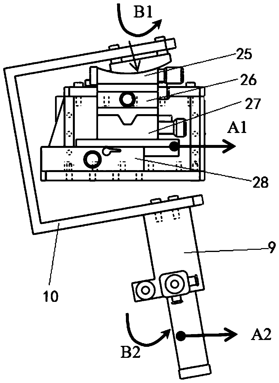
[0052] to combine Figure 1 to Figure 4 As shown, the four-dimensional adjustment device for the optical centering instrument of this embodiment includes a four-dimensional adjustment mechanism 2, a connecting frame 4, and an adapter frame 10; the four-dimensional adjustment mechanism 2 includes an X-axis angle adjustment platform 25 arranged sequentially from top to bottom , Y-axis angle adjustment platform 26, X-axis translation adjustment platform 27 and Y-axis translation adjustment platform 28, and constitute a whole.

[0053] Among them, the X-axis angle adjustment table 25 has the same structure as the Y-axis angle adjustment table 26, and the direction of the angle adjustment center axis is vertical, and the adjustment range is -10°~10°; the X-axis translation adjustment table 27 and the Y-axis translation adjustment table 28 have the same structure, and the translation directions are perpendicular to each other, and the adjustment range is -37.5mm to 37.5mm, which mee...

Embodiment 2

[0061] combine Figure 2 to Figure 4 As shown, the structure of the four-dimensional adjustment device of this embodiment is basically the same as that of Embodiment 1, the difference is that the adapter frame 10 includes an upper horizontal plate 101, an adapter vertical plate 102 and a lower horizontal plate 103; the upper horizontal plate 101 and the lower horizontal plate 103 are located on the same side of the transfer vertical plate 102, and one end of the upper horizontal plate 101 and the lower horizontal plate 103 are respectively vertically connected with the two ends of the transfer vertical plate 102 to form a C-shaped structure of the transfer frame 10, The upper end surface of the X-axis angle adjustment platform 25 is connected with the lower end surface of the upper horizontal plate 101; the optical centering device 9 is connected with the lower end surface of the lower horizontal plate 103; Located below the four-dimensional adjustment mechanism 2 , the adjust...


PUM


Abstract

The invention relates to an adjusting device for an optical centering instrument. The adjusting device aims at solving the problems of low adjustment precision and inconvenient operation of the optical centering instrument in the prior art, realizing rapid and accurate adjustment of the translation amount and the inclination angle of the optical centering instrument in the optical centering processing process, and improving the efficiency of centering machining. The adjusting device comprises a four-dimensional adjusting mechanism, a connecting frame and a multitap frame, the four-dimensionaladjusting mechanism comprises an X-axis angle adjusting table, a Y-axis angle adjusting table, an X-axis translation adjusting table and a Y-axis translation adjusting table which are sequentially arranged from top to bottom, the lower end of the Y-axis translation adjusting table is connected with an upper end platform of a vertical lathe through the connecting frame, the upper end of the X-axisangle adjusting table is connected with the optical centering instrument through the multitap frame, and the optical centering instrument is located below the Y-axis translation adjusting table. According to the adjusting device, the optical centering instrument and the four-dimensional adjusting mechanism are connected together, and through adjustment of the four-dimensional adjusting mechanism,two directional translation and two directional angles of the optical centering instrument can be adjusted.

Description

technical field [0001] The invention relates to an optical centering instrument, in particular to an adjustment device for the optical centering instrument. Background technique [0002] The optical centering instrument is a commonly used instrument in the optical centering process. Its function is to ensure the accuracy of the optical centering process by monitoring the sway of the self-collimation image of the spherical center of the optical element. [0003] The centering processing of the large-aperture optical mirror group is generally carried out on a vertical lathe, and the optical centering device is suspended on the top of the lathe to monitor the self-collimation image of the center of the sphere. The entire centering process is as follows: [0004] 1. Place a circular plane mirror on the turntable of the lathe, and draw a crosshair in the center of the mirror. Adjust the position of the reflector to ensure that when the turntable rotates, the radial and end runo...

Claims


Application Information

Patent Timeline
Patent Type & Authority Applications(China)
IPC IPC(8): B26D7/27B28D7/00
CPCB26D7/27B28D7/00Y02P40/57
Inventor 雷昱康世发付兴王鹏
Owner XI'AN INST OF OPTICS & FINE MECHANICS - CHINESE ACAD OF SCI
Learn More