
Monitoring device capable of adjusting shooting angle

A technology of shooting angle and monitoring device, which is applied to the body of the camera, parts of the color TV, parts of the TV system, etc. It can solve the problems of not being able to meet the monitoring needs and the small adjustable range of the camera, so as to improve the stability performance, ensure the effect of monitoring, and ensure the effect of safety

Inactive Publication Date: 2019-12-10
郑州神盾智能科技有限公司
View PDF0 Cites 3 Cited by
  • Summary
  • Abstract
  • Description
  • Claims
  • Application Information

AI Technical Summary

Problems solved by technology

[0004] The purpose of the present invention is to provide a monitoring device with adjustable shooting angle in order to solve the problem that the adjustable range of the camera of the existing monitoring equipment is too small to meet the monitoring requirements under many special conditions.

Method used


Image

  • Monitoring device capable of adjusting shooting angle
  • Monitoring device capable of adjusting shooting angle

Examples


Embodiment 1

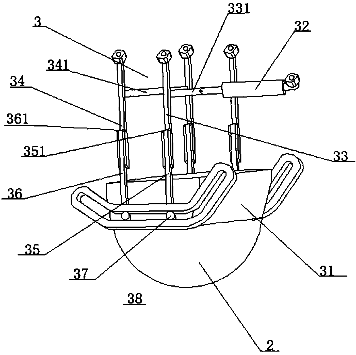
[0023] A monitoring device with adjustable shooting angle, comprising a mounting base 1 and a camera assembly 2, characterized in that: an adjustment mechanism 3 is provided between the camera assembly 2 and the installation base 1, and the adjustment mechanism 3 includes a mounting block 31 and A cylinder 32 hinged with the installation base 1, the output shaft of the cylinder 32 is hinged with a front swing slide rail 33, one end of the front swing slide rail 33 is hinged with the installation base 1, and the installation base 1 is also hinged There is a rear swing slide rail 34 parallel to the front swing slide rail 33, and a front slide bar 35 is arranged inside the front swing slide rail 33, and the front slide bar 35 can move along the front swing slide rail 33 in the front swing slide rail 33. The length direction of the rear swing slide rail 34 is provided with a rear slide bar 36, and the rear slide bar 36 can move along the length direction of the rear swing slide rai...

Embodiment 2

[0025] On the basis of Embodiment 1, the front swing slide rails 33 and the rear swing slide rails 34 are provided with two groups, and the two groups of front swing slide rails 33 are connected by the front connecting rod 331, and the output shaft of the cylinder 32 Hinged at the center of the front link 331 , the rear swing slide rails 34 are connected by the rear link 331 .

Embodiment 3

[0027] On the basis of Embodiment 1 or 2, one end of the front slide bar 35 protruding from the front swing slide rail 33 is provided with a front limiter plate 351 that limits the maximum stroke of the front slide bar 35, and the rear slide bar 36 stretches out. One end of the swing slide rail 34 is provided with a rear limiting plate 361 for limiting the maximum stroke of the rear sliding rod 36 .


PUM


Abstract

The invention discloses a monitoring device capable of adjusting the shooting angle. The monitoring device comprises a mounting base and a camera assembly, and is characterized in that an adjusting mechanism is arranged between the camera assembly and the mounting base and comprises a mounting block and an air cylinder which is hinged to the mounting base; an output shaft of the air cylinder is hinged to a front swing sliding rail; one end of a front swinging sliding rail set is hinged to the mounting base; a rear swing sliding rail in parallel with the front swing sliding rail is hinged to the mounting base; a front sliding rod is arranged in the front swing sliding rail; a rear sliding rod is arranged in the rear swing sliding rail; pulleys are hinged to the bottoms of the front slidingrod and the rear sliding rod; fixed adjusting grooves are formed outside the pulleys; the pulleys can move in the adjusting grooves and in the track direction of the adjusting grooves; the mounting block is arranged on the inner side of the pulleys; the pulleys are arranged on the two sides of the mounting block through connecting rods; the camera assembly is arranged at the bottom of the mountingblock; and a camera is wider in shooting angle, so that and the monitoring effect of the monitoring device is ensured.

Description

technical field [0001] The invention relates to the field of monitoring devices, in particular to a monitoring device capable of adjusting shooting angles. Background technique [0002] At present, the front-end products of security monitoring mainly include several categories such as fast balls, uniform speed balls, bullet cameras and dome cameras. [0003] The monitoring equipment is generally installed in the middle or corner of the ceiling of the room. The base of the monitoring equipment is in contact with the ceiling and is fixedly installed. Direction, in order to achieve the best shooting angle, but the adjustable range of the existing monitoring equipment camera is too small to meet the monitoring needs under many special conditions. Contents of the invention [0004] The purpose of the present invention is to provide a monitoring device with an adjustable shooting angle in order to solve the problem that the adjustable range of the camera of the existing monitor...

Claims


Application Information

Patent Timeline
IPC IPC(8): F16M11/18F16M11/04F16M13/02G03B17/56H04N5/225H04N7/18
CPCF16M11/18F16M11/04F16M13/027H04N7/18G03B17/561H04N23/50
Inventor 孙恒
Owner 郑州神盾智能科技有限公司
Learn More