Electric vehicle discharge control device and discharge control method
A technology of electric vehicle and discharge control, which is applied in the direction of secondary battery charging/discharging, secondary battery repair/maintenance, AC network load balancing, etc., and can solve problems such as grid system burden, and achieve peak shaving and valley filling, simple and intuitive Operation screen, the effect of flexible discharge mode control
- Summary
- Abstract
- Description
- Claims
- Application Information
AI Technical Summary
Problems solved by technology
Method used
Image

Examples
Embodiment 1
[0055] In the first embodiment, the fixed setting mode is adopted as the first mode. The feature of this mode is that the daily driving distance of the electric vehicle is basically kept constant, and the user sets at least one of the fixed minimum battery remaining state of charge (minimum SoC) after discharge and the fixed daily cumulative maximum discharge capacity according to the driving distance. either side. By adopting this mode, the user does not need to perform operations every time, and the burden on the user can be reduced.
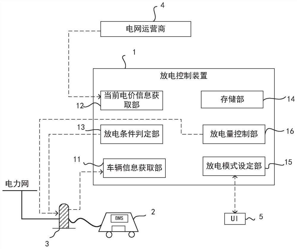
[0056] In the first embodiment, the storage unit 14 stores the current electricity price information, vehicle information and discharge mode setting as shown in Table 1 in the form of a database.
[0057] Table 1
[0058]
[0059]
[0060] According to Table 1, user A sets the minimum SoC to 40% through the setting screen of the UI, that is, keeps the SoC above 40% all the time, and stops discharging when the SoC reaches 40% during dis...
Embodiment 2
[0072] In the second embodiment, the checking mode of each discharge is adopted as the second mode. The feature of this mode is that the daily driving distance of electric vehicles varies greatly, and the user can set the remaining state of charge (SoC) of the battery after each discharge. By adopting this mode, users can flexibly set according to their own needs to obtain the greatest economic benefits.
[0073] In the second embodiment, the storage unit 14 stores the current electricity price information, vehicle information and discharge mode setting as shown in Table 2 in the form of a database.
[0074] Table 2
[0075]
[0076] According to Table 2, each time users D-F discharge, they perform a discharge confirmation operation, and set the SoC after discharge according to their own needs.
[0077] The following combination Figure 5 A diagram illustrating the operation process of the second embodiment of the discharge control device for electric vehicles. In Embodim...
Embodiment 3
[0092] The only difference between this embodiment 3 and embodiment 2 is that the vehicle information acquired by the vehicle information acquisition unit 11 also includes the past driving information of the electric vehicle 2 and the past battery state information, and the discharge mode adopts the third mode, and the third mode , the user inputs the next travel plan, and the discharge mode setting unit 15 can calculate the remaining state of charge (SoC) of the battery required for the travel plan based on the past travel information of the electric vehicle 2 and the past battery state information. as the lowest remaining state of charge of the battery after discharge.
[0093] Specifically, as the next driving plan, the user may directly input the next driving distance, or may input the current location and driving destination.
[0094] When using this mode, the user only needs to input the driving plan to ensure the required minimum battery power. The operation is simple a...
PUM
 Abstract
Description
Claims
Application Information
 - R&D
- Intellectual Property
- Life Sciences
- Materials
- Tech Scout
- Unparalleled Data Quality
- Higher Quality Content
- 60% Fewer Hallucinations
Browse by: Latest US Patents, China's latest patents, Technical Efficacy Thesaurus, Application Domain, Technology Topic, Popular Technical Reports.
© 2025 PatSnap. All rights reserved.Legal|Privacy policy|Modern Slavery Act Transparency Statement|Sitemap|About US| Contact US: help@patsnap.com