
Patsnap Eureka
For R&D, Patsnap Eureka makes reading and utilizing patents & technical documents easy.
Patsnap Eureka AIR
Designed for self-driven R&D workflows. Generate viable solutions, solve complex R&D challenges, empower your innovation with AI.

Patsnap Eureka Materials
Designed for material experts only. Revolutionize your material R&D, from search, analyze, to developing new materials.

TechResearch
Generate reliable direction feasibility study reports for your R&D in just a few steps.

TechSeek
Discover and master advanced knowledge NOW. Basics, ideas, possibilities, all at once.

TechMind
As an expert in R&D Theories, TechMind can generates customized viable solutions instantly.

TechRisk
Analyze your overall solution with one click, know your potential R&D risks in advance.

TechMonitor
Get weekly tech updates, stay abreast of the latest tech innovations and key insights.
Combustion device
A combustion device and combustion chamber technology, which is applied to burners, combustion types, combustion methods, etc., can solve the problems of poor combustion state and increase of carbon monoxide concentration in combustion exhaust gas, maintain combustion performance, and inhibit the increase of carbon monoxide concentration. Effect
- Summary
- Abstract
- Description
- Claims
- Application Information
AI Technical Summary
Problems solved by technology
Method used
Image

Examples
Embodiment Construction
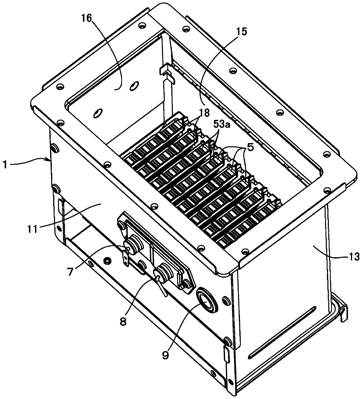
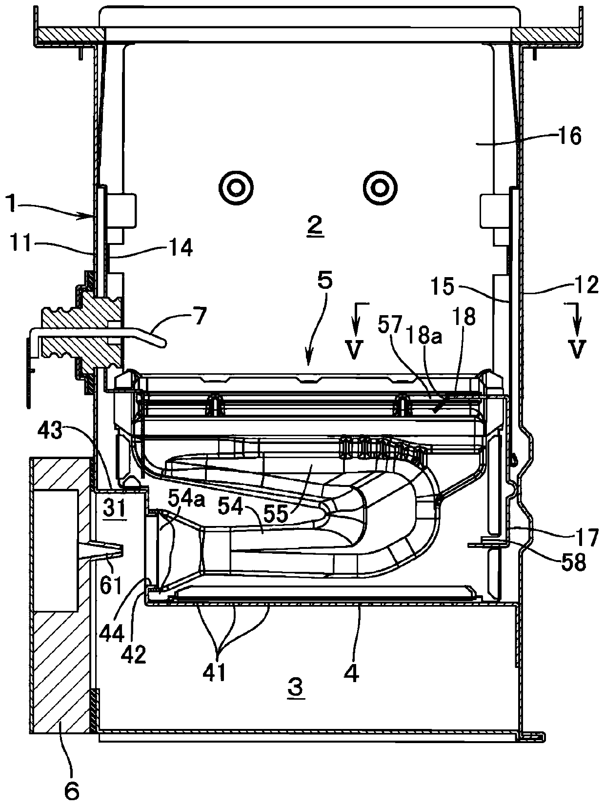
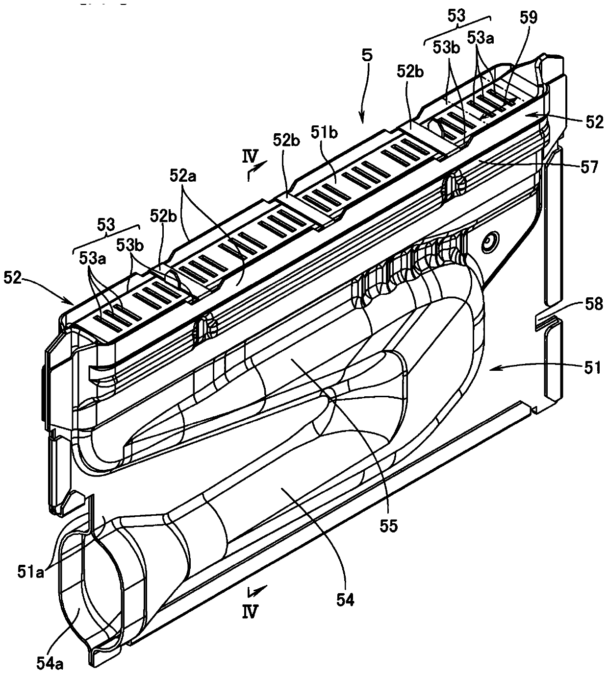
[0020] refer to figure 1 , figure 2 , 1 denotes a combustion case constituting a combustion device including a heat source machine for hot water supply. The upper surface of the combustion case 1 is open, and a heat exchanger for supplying hot water (not shown) as an object to be heated is provided above the combustion case 1 . In the combustion housing 1, a combustion chamber 2 and an air supply chamber 3 on the lower side of the combustion chamber 2 are arranged. The air supply chamber 3 is separated from the combustion chamber 2 by a partition plate 4 . In the combustion chamber 2, a plurality of burners 5 long in the front-rear direction are arranged side by side with a gap in the lateral direction.
[0021] A combustion fan (not shown) is connected to the bottom surface of the air supply chamber 3 , and air is supplied to the air supply chamber 3 from the combustion fan. A plurality of distribution holes 41 are formed in the partition plate 4 . And the air supplied ...
PUM
 Abstract
Description
Claims
Application Information
 - R&D Engineer
- R&D Manager
- IP Professional
- Industry Leading Data Capabilities
- Powerful AI technology
- Patent DNA Extraction
Browse by: Latest US Patents, China's latest patents, Technical Efficacy Thesaurus, Application Domain, Technology Topic, Popular Technical Reports.
© 2024 PatSnap. All rights reserved.Legal|Privacy policy|Modern Slavery Act Transparency Statement|Sitemap|About US| Contact US: help@patsnap.com