Centrifuge Drive Protection Circuit

A technology for protecting circuits and drivers, applied in the electronic field, can solve problems such as damage, imbalance, and lack of output current of the centrifuge driver

Active Publication Date: 2021-07-30
SHENZHEN SUNFAR ELECTRIC TECH
View PDF13 Cites 0 Cited by
  • Summary
  • Abstract
  • Description
  • Claims
  • Application Information

AI Technical Summary

Problems solved by technology

[0002] The traditional centrifuge driver protection scheme uses the sampling results to calculate the three-phase current unbalance degree to perform output current unbalance protection or does not have the protection function of output current unbalance; the overcurrent protection scheme generally uses the voltage signal obtained after current sampling After rectification and filtering, the result is compared with the preset protection point voltage, and the protection signal is output to the MCU. This may cause a maximum 30-degree phase delay between the fault current peak value and the protection point signal, and the fault point voltage has a maximum The 13.3% error is not conducive to the protection of the centrifuge drive, which will easily lead to an increased risk of damage to the centrifuge drive

Method used


Image

  • Centrifuge Drive Protection Circuit
  • Centrifuge Drive Protection Circuit
  • Centrifuge Drive Protection Circuit

Examples


Embodiment Construction

[0040] The following will clearly and completely describe the technical solutions in the embodiments of the present invention with reference to the accompanying drawings in the embodiments of the present invention. Obviously, the described embodiments are some of the embodiments of the present invention, but not all of them. Based on the embodiments of the present invention, all other embodiments obtained by persons of ordinary skill in the art without creative efforts fall within the protection scope of the present invention.

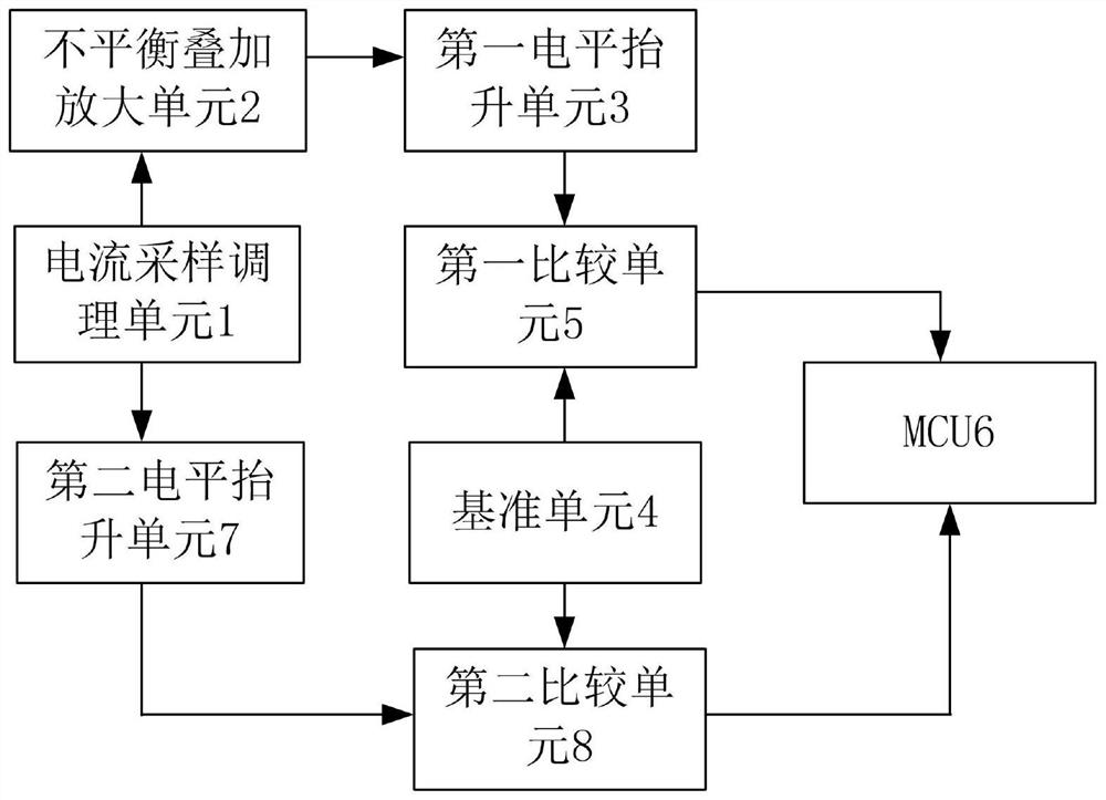
[0041] In one embodiment, as figure 1 As shown, the centrifuge driver protection circuit includes a current sampling and conditioning unit 1, an unbalanced superposition amplification unit 2, a first level raising unit 3, a reference unit 4, a first comparison unit 5, an MCU 6, a second level raising unit 7 and a second comparison unit 8;

[0042] The input end of the unbalanced superposition amplifying unit 2 is connected to the output end of the cur...


PUM


Abstract

The invention discloses a protection circuit for a centrifuge driver. The circuit includes a current sampling and conditioning unit, an unbalanced superposition amplification unit, a first level raising unit, a reference unit, a first comparison unit, a second level raising unit, and a second comparison unit. unit and MCU; the input end of the unbalanced superposition amplification unit is connected to the output end of the current sampling conditioning unit, the input end of the first level raising unit is connected to the output end of the unbalanced superposition amplification unit, and the input ends of the first comparison unit are respectively It is connected with the output end of the first level raising unit and the output end of the reference unit, and the output end of the first comparison unit is connected with the designated pin of the MCU; the input end of the second level raising unit is connected with the output end of the current sampling conditioning unit The input terminal of the second comparison unit is connected with the output terminal of the second level raising unit and the output terminal of the reference unit respectively, and the output terminal of the second comparison unit is connected with the designated pin of the MCU to reduce the damage of the centrifuge driver. risk.

Description

technical field [0001] The invention relates to the field of electronic technology, and more specifically relates to a centrifuge drive protection circuit. Background technique [0002] The traditional centrifuge driver protection scheme uses the sampling results to calculate the three-phase current unbalance degree to perform output current unbalance protection or does not have the protection function of output current unbalance; the overcurrent protection scheme generally uses the voltage signal obtained after current sampling After rectification and filtering, the result is compared with the preset protection point voltage, and the protection signal is output to the MCU. This may cause a maximum 30-degree phase delay between the fault current peak value and the protection point signal, and the fault point voltage has a maximum The error of 13.3% is not conducive to the protection of the drive of the centrifuge, which easily leads to an increased risk of damage to the driv...

Claims


Application Information

Patent Timeline
Patent Type & Authority Patents(China)
IPC IPC(8): B04B9/00
CPCB04B9/00
Inventor 黄骏
Owner SHENZHEN SUNFAR ELECTRIC TECH
Why Eureka
Try Eureka