
Bendable intervention valve conveying system

A delivery system and bending adjustment technology, which is applied in the field of medical devices, can solve problems such as difficult to meet the needs of bending adjustment, long interventional devices, laborious operation, etc., and achieve the effect of improving controllability

Pending Publication Date: 2019-10-01
VENUS MEDTECH (HANGZHOU) INC
View PDF2 Cites 18 Cited by
  • Summary
  • Abstract
  • Description
  • Claims
  • Application Information

AI Technical Summary

Problems solved by technology

[0008] Even if the pull wire is used in the prior art, especially the pull wire is threaded and bound in the pipeline or channel as a whole, so the interventional instrument that needs to be greatly adjusted or the distal end of the sheath is relatively long, In hard conditions, it is difficult to meet the needs of bending adjustment, and because the bending adjustment is limited by the magnitude of the torque and the deformation of the surrounding parts where the pulling wire is located, the operation is more laborious

Method used


Image

  • Bendable intervention valve conveying system
  • Bendable intervention valve conveying system
  • Bendable intervention valve conveying system

Examples


Embodiment Construction

[0112] The present application will be further explained below in conjunction with specific examples.

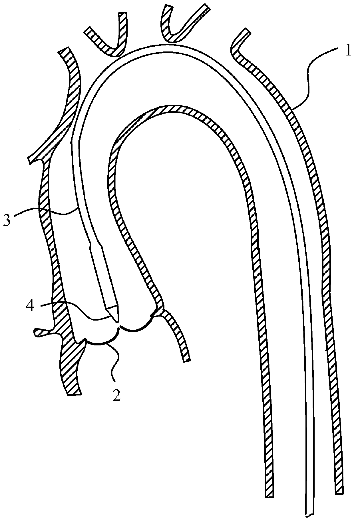
[0113] see figure 1 , in the prior art, taking the replacement of the aortic valve as an example, after the interventional device is loaded, it enters the aorta 1 under the guidance of the guide head 1 of the delivery system, passes through the aortic arch and is adjacent to the position of the aortic valve 2, and the interventional device is placed in the sheath before release. under the wrapping of the tube body 3, figure 1 2 shows the position and orientation of the aortic valve 2 with a normal physiological structure. Using the sheath that can be bent at the distal end in the prior art, the distal end of the delivery system can be bent, and the guide head 4 points to the aortic valve 2 .

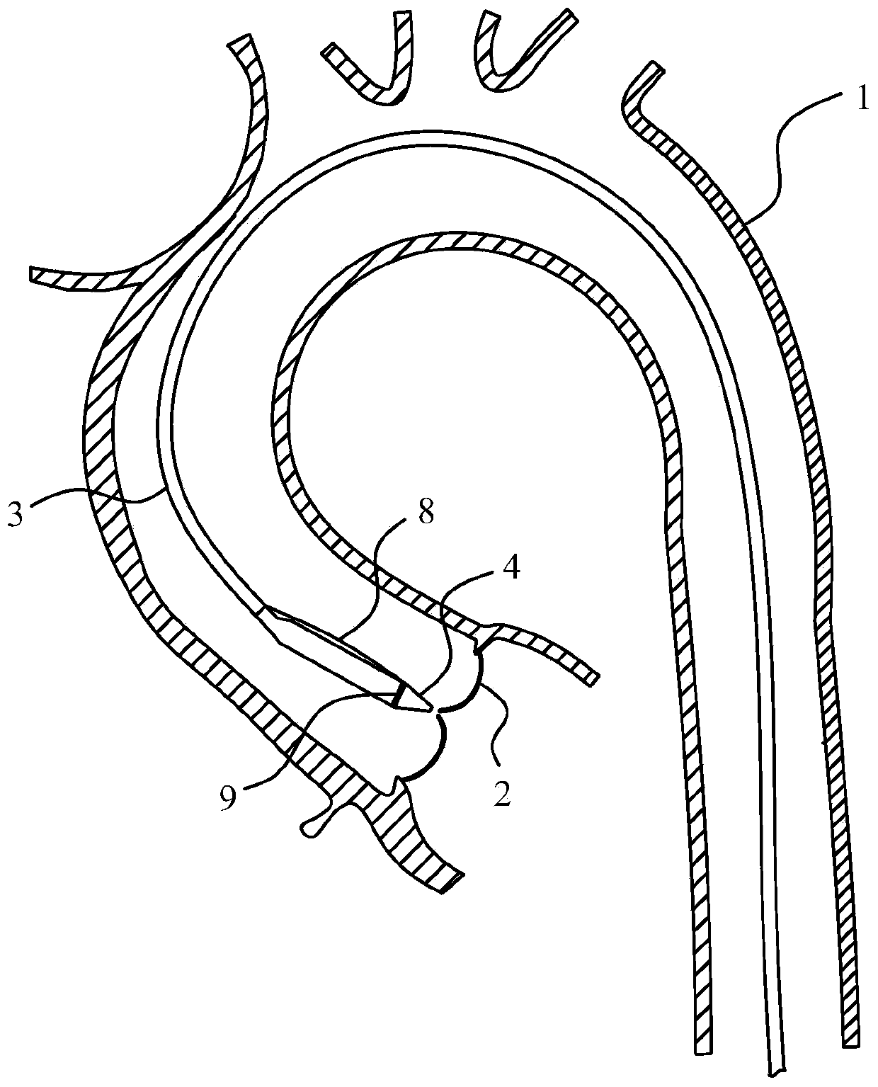
[0114] see Figure 2a , due to lesions, some special occasions may require a larger bending range at the distal end of the delivery system, such as Figure 2a The orientation of the...


PUM


Abstract

The invention discloses a bendable intervention valve conveying system. The system comprises a bendable sheathing canal, a sheath core placed in the bendable sheathing canal and an operation handle connected with the near ends of the bendable sheathing canal and the sheath core, the bendable sheathing canal comprises a canal body and a traction wire, and the canal body is provided with a far end and a near end; the far end of the canal body is bent under pulling of the traction wire, and the near end of the traction wire is connected with the operation handle; the operation handle comprises afixing body of a hollow structure, a traction part slidingly installed in the fixing body and connected with the traction wire, a driving mechanism installed on the fixing body and used for driving the traction part to move and a control mechanism installed on the fixing body and used for driving the bendable sheathing canal to move. The traction wire in the bendable sheathing canal is provided with one segment outside the sheathing canal body in a free mode, during traction, the traction wire is in a posture which provides convenience for force application, and the operation safety and flexibility are improved.

Description

technical field [0001] The application belongs to the technical field of medical devices, and in particular relates to an adjustable bending interventional valve delivery system. Background technique [0002] Interventional surgery causes little trauma to the human body and is less invasive. It is a medical technology that has been rapidly emerging and promoted in recent years. A channel is established between the lesion site and the external operation terminal to introduce diagnostic and treatment instruments, drugs, interventional instruments, etc. to the lesion site. The interventional diagnosis and treatment sheath has a distal end and a proximal end. The distal end can enter the vascular system of the human body, and the proximal end is connected to the operating handle. Other auxiliary instruments are punctured into the blood vessel, and the physician controls the distal end of the sheath along the pre-established guide wire track to the lesion to release drugs and in...

Claims


Application Information

Patent Timeline
IPC IPC(8): A61F2/24A61F2/95
CPCA61F2/2418A61F2/2466A61F2/95A61F2250/0098
Inventor 张志飞王媛茹吴世广葛彰凯
Owner VENUS MEDTECH (HANGZHOU) INC
Learn More