X-shaped, V-shaped and Y-shaped special-shaped component assembly method

A technology of special-shaped components and components, which is applied in the field of assembly of XVY-shaped special-shaped components, can solve problems such as difficulty in assembling special-shaped components, and achieve the effects of convenient splicing, reasonable force, and guaranteed quality

Active Publication Date: 2019-09-20
CHONGQING CONSTR ENG GRP +2
View PDF7 Cites 0 Cited by
  • Summary
  • Abstract
  • Description
  • Claims
  • Application Information

AI Technical Summary

Problems solved by technology

[0003] The purpose of the present invention is to provide a method for assembling XVY-shaped special-shaped components to solve the problem of difficulty in assembling special-shaped components in the prior art

Method used


Image

  • X-shaped, V-shaped and Y-shaped special-shaped component assembly method
  • X-shaped, V-shaped and Y-shaped special-shaped component assembly method
  • X-shaped, V-shaped and Y-shaped special-shaped component assembly method

Examples


Embodiment 1

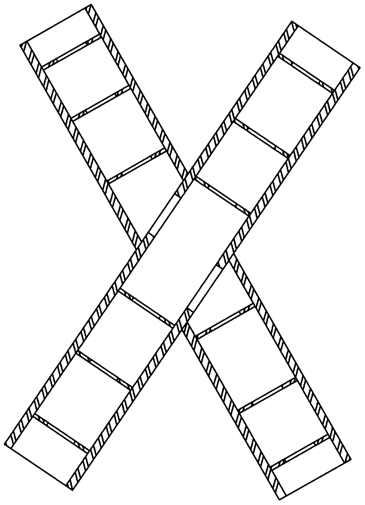
[0023] Embodiment 1: XVY shape special-shaped member assembling method, comprises the following steps:

[0024] Step A: According to the results of measuring the position of the top surface of the installed components, judge the deviation value of the installed components, and then carry out the adaptability of the bottom connection surface of the special-shaped components (X-shaped, V-shaped or Y-shaped) to be installed Adjust machining (short stock and beveling) to compensate for deviations in installed components;

[0025] Step B: Use at least 3 length-adjustable slings to hoist the special-shaped component, and the hoisting points form at least a triangle; the sling is equipped with a chain block that can adjust the length of the sling; the lifting points are all close to the sides of the special-shaped component The edge of the outer contour increases the angle between the lifting ropes, which is conducive to increasing the stability of the special-shaped component after ...

Embodiment 2

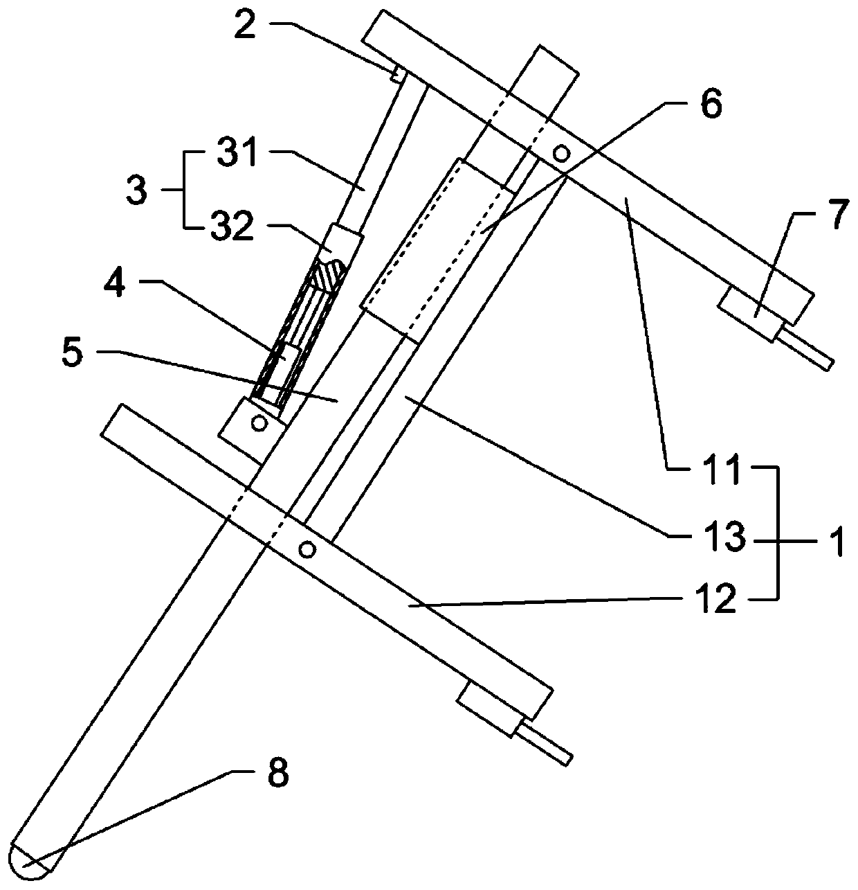
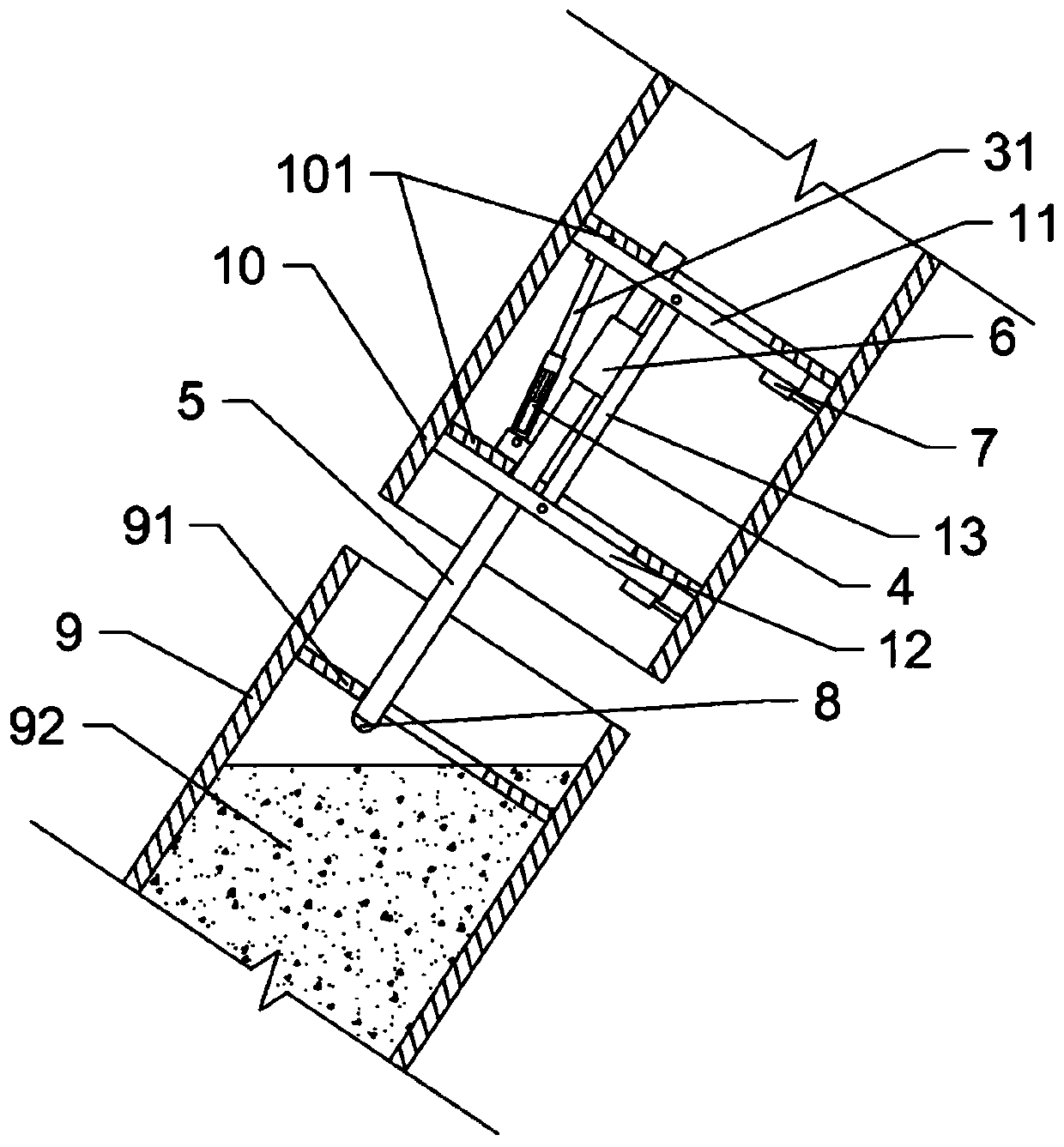
[0031] The only difference from Implementation 1 is that in step B, an auxiliary positioning mechanism is set at the bottom of the special-shaped member 10 to be installed, such as figure 1 and figure 2 As shown, the auxiliary positioning mechanism includes a push rod 5, and a universal wheel 8 is installed on the lower end of the push rod 5; A connecting rod 13 is hinged between the supporting frame 11 and the lower supporting frame 12. A sleeve 6 is welded and fixed on the connecting rod 13. The sleeve 6 is slidably sleeved on the push rod 5. The sliding fit can realize the relative sliding between the ejector rod 5 and the support frame 1; the lower ends of the upper support frame 11 and the lower support frame 12 are all bolted to the positioning jack 7. A telescopic mechanism 3 is arranged between the middle part of the push rod 5 and the upper end of the upper support frame 11. The telescopic mechanism 3 includes a sleeve 32 and a movable rod 31. The movable rod 31 is...


PUM


Abstract

The invention belongs to the technical field of construction steel structure installation, and particularly discloses an X-shaped, V-shaped and Y-shaped special-shaped component assembly method. The X-shaped, V-shaped and Y-shaped special-shaped component assembly method comprises the following steps that step A, a bottom joint surface of a special-shaped component is subjected to adaptation adjustment and processing according to the top surface position of an installed component; step B, at least three length-adjustable lifting ropes are used for lifting the special-shaped component, and lifting points for lifting at least form a triangle; step C, the length of the lifting ropes is adjusted for splicing the bottom of the special-shaped component; step D, the special-shaped component is fixed with a rigid support, and top coordinates of the special-shaped component are measured and positioned; step E, the bottom surface of the special-shaped component is subjected to welded connection; and step F, when welding seams in the step E are cooled, and support and fixation of the lifting ropes and the rigid support to the special-shaped component are released. The X-shaped, V-shaped and Y-shaped special-shaped component assembly method solves the problem that in the prior art, the assembly of the special-shaped component is relatively difficult.

Description

technical field [0001] The invention belongs to the technical field of building steel structure installation, in particular to a method for assembling XVY-shaped special-shaped components. Background technique [0002] In the construction of steel structures in construction projects, sometimes special-shaped components are encountered, such as: column components with X-shaped, V-shaped or Y-shaped shapes, such as Figure 3 to Figure 5 As shown, such components are mostly connected by large-diameter circular steel pipes, and the interior of the components needs to be poured with concrete. Therefore, a ring-shaped support plate will be set inside the components to strengthen the rigidity of the components and prevent the cross-section of the components from being damaged during transportation. Deformation occurs during installation and installation. Therefore, such components are generally relatively large in size and mass, and have large inertia during hoisting and handling, m...

Claims


Application Information

Patent Timeline
IPC IPC(8): E04G21/14
CPCE04G21/14
Inventor 曾磊陈秉瑞徐立刘懿姚文祥秦文军
Owner CHONGQING CONSTR ENG GRP
Why Eureka
Try Eureka