
Strain clamp for stranded carbon fiber composite core wire

A tension-resistant clamp and carbon fiber technology, which is applied in the direction of adjusting/maintaining mechanical tension, can solve the problems of non-adjustable crimping force, small grip force, and inability to meet the requirements of stranded carbon fiber composite core wire connection, fixing, and tensioning, etc.

Inactive Publication Date: 2019-09-17
NORTH CHINA ELECTRIC POWER UNIV (BAODING) +1
View PDF6 Cites 6 Cited by
  • Summary
  • Abstract
  • Description
  • Claims
  • Application Information

AI Technical Summary

Problems solved by technology

[0004] At present, neither the traditional domestic tension clamps nor the existing carbon fiber composite core wire tension clamps can meet the requirements of connecting, fixing, and tensioning the stranded carbon fiber composite core wires on the terminal tower. Easy to slip, low strength, and non-adjustable crimping force, so it is imperative to design a new strain clamp structure suitable for stranded carbon fiber composite core conductors

Method used


Image

  • Strain clamp for stranded carbon fiber composite core wire
  • Strain clamp for stranded carbon fiber composite core wire
  • Strain clamp for stranded carbon fiber composite core wire

Examples


Embodiment Construction

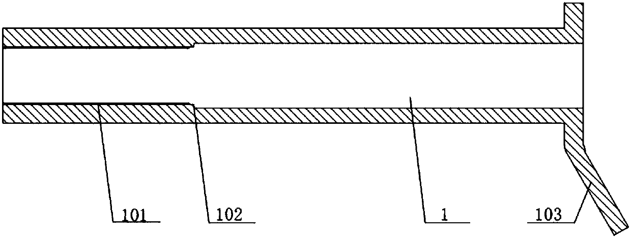
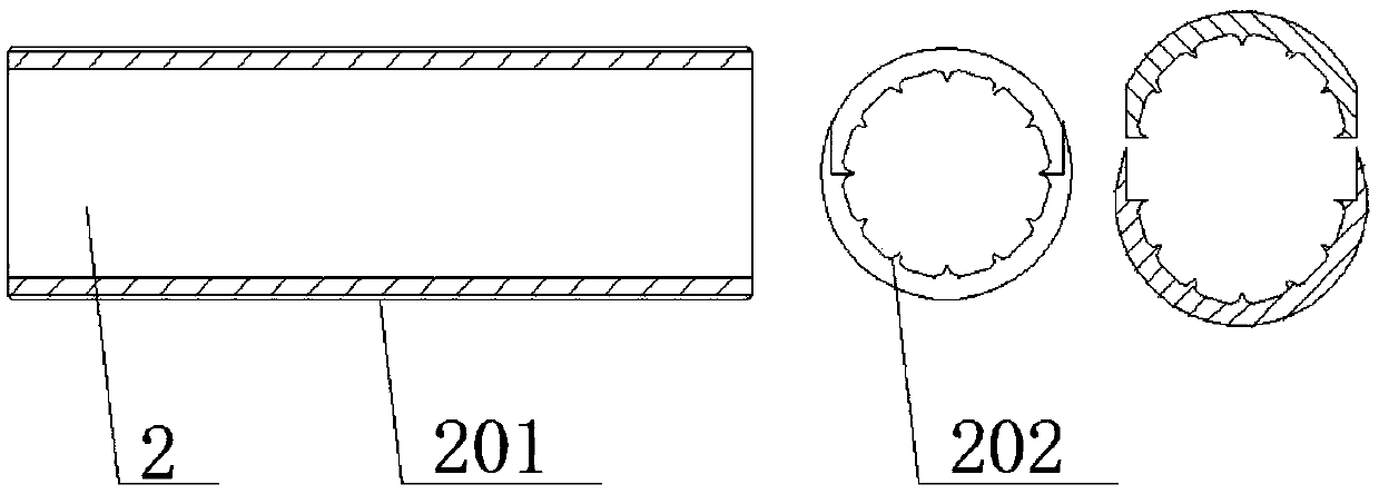
[0020] refer to figure 1 : Put the end of the stranded carbon fiber composite core wire (6) through the inner liner (2), and then through the tension clamp body (1); The large port of the clamp body is placed at the step (102) on its inner surface, which is used to block the inward movement of the composite carbon core protective tapered sleeve (4); next, pass the stranded carbon fiber composite core (7) through the central circular retaining ring (3) Then penetrate the stranded carbon core protective cone sleeve (4) to make the two closely match; then screw the tightly matched stranded carbon fiber composite core (7) and the stranded carbon core protective cone sleeve (4) into this A new type of steel anchor (5), which realizes tight fit through tapered threads, and realizes different The selection of the pressure value, so that the stranded carbon core protection tapered sleeve locks the stranded carbon fiber composite core; then move the end of the strain clamp body (1) wh...


PUM


Abstract

The invention relates to a strain clamp for a stranded carbon fiber composite core wire. The strain clamp is composed of a wire clamp body, an inner lining pipe, a middle through circular check ring, a stranded carbon core protection taper sleeve and a novel steel anchor. The wire clamp body is matched and connected with the inner lining pipe; the middle through circular check ring is arranged at the step of the inner surface of the wire clamp body; the novel steel anchor is arranged at the internal portion of the side, provided with a drainage plate, of the wire clamp body; the taper of the stranded carbon core protection taper sleeve is consistent with the that of the inner surface of the steel anchor, and the stranded carbon core protection taper sleeve is matched and connected with the steel anchor through threads; the steel anchor is tightly screwed, when the port of the steel anchor reaches a certain scale marked at the outer surface of the stranded carbon core protection taper sleeve, the clamping force of the wire clamp to the carbon fiber core can reach a certain value to achieve the function of the adjustable stranded carbon core by the wire clamp. The strain clamp for a stranded carbon fiber composite core wire is a novel strain clamp, can effectively avoid the damage and fracture problems of stranded carbon cores of wires and can achieve the function of adjusting the pressing force of the stranded carbon cores within a certain range; and moreover, the strain clamp has the advantages of the scientific and reasonable structure, the stable performance and the capability of effectively reducing labor intensity.

Description

technical field [0001] The invention relates to an electric power fitting, which is a strain clamp used for connecting, fixing and tensioning stranded carbon fiber composite core conductors on overhead power transmission lines and substation towers. Background technique [0002] With the rapid development of society and economy, land resources are becoming increasingly scarce, and the approval and construction of new channels for overhead transmission lines has become a prominent problem in power grid construction. Due to the rapid economic development in some areas, the electricity load has increased exponentially. The transmission capacity of the original transmission lines can no longer meet the rapid growth of the load. It is imperative to replace the wires, thicken the wires, and develop new types of wires. [0003] At present, carbon fiber composite core conductors have been widely used in the transformation of power grids and the transformation of overhead transmissio...

Claims


Application Information

Patent Timeline
IPC IPC(8): H02G7/02
CPCH02G7/02
Inventor 周超赵士杰刘衍平陈作宋玉旺周鑫林宏帅雷雨刘荣见杨坤池
Owner NORTH CHINA ELECTRIC POWER UNIV (BAODING)
Learn More