An impeller assembly and solid and liquid mixing equipment using the same

A liquid mixing and impeller technology, which is applied to mixers, mixers, mixing methods and other directions with rotating stirring devices, can solve the problems of reduced processing speed and capacity, large area and volume, and low speed, and can offset the decline in fluidity. , The effect of simplifying the production process and improving the processing speed

Active Publication Date: 2021-07-20
SHENZHEN SHANGSHUI INTELLIGENT CO LTD
View PDF9 Cites 0 Cited by
  • Summary
  • Abstract
  • Description
  • Claims
  • Application Information

AI Technical Summary

Problems solved by technology

However, through the cumulative verification of actual production, although the mixing effect of the above-mentioned mixing equipment is improved compared with the old equipment, there are still several defects: First, because ordinary blades are used to beat the powder onto the dispersion cylinder, there is no correcting of the powder. Targeted treatment of the gas wrapped around the powder body, the infiltration effect of the powder body is poor, and there are more residual gases on the surface
In the state where the air on the surface of the powder is not exhausted to the maximum extent, the dispersing cylinder intervenes in the pre-mixing work prematurely, resulting in insufficiently infiltrated powder agglomerates being thrown onto the dispersing cylinder 41 by the mixing blade 44, which is easy to block The dispersing hole 42 cannot achieve the best premixing effect, which affects the subsequent dispersing process
Second, due to the working principle, the dispersing cylinder must be installed from top to bottom. Its area and volume are very large, and it needs to rotate with the main shaft. The structure is complex and energy consumption is high.
Third, because the dispersing cylinder participates in the entire infiltration and dispersion process, when the powder enters the area where the mixing blade and the dispersing cylinder are set, many powder agglomerates are not fully dispersed. At the same time, the blades and the wall of the cylinder The distance is very close, causing large agglomerates to be directly hit on the dispersing cylinder before they can be broken up, causing the dispersing holes to be blocked, and the processing speed and capacity of the entire equipment to decrease, which cannot meet the requirements of rapid production.
Fourth, since the mixing blade, dispersing cylinder and dispersing disc use the same main shaft and motor, and the truncated conical impeller is not used, the linear speed of the bottom edge of the impeller is not fast, the mixing and throwing effects are affected, and it cannot be formed at the discharge port. Effective vacuum, slow downflow of the suspension, unsatisfactory raw material processing speed
Fifth, the direction in which the suspension flows is consistent with the direction in which the dispersion cylinder is set, and there is no impeller in the lower part, the speed at which the suspension enters the lower dispersion hole is low, and the small shear force affects the dispersion effect, and if the length of the dispersion cylinder is not long enough , there will be some suspensions that cannot enter the dispersion holes at all
The mixing device is actually similar to the technical solution of the previous patent, which is equivalent to adding an independent discharge mechanism on the basis of the previous patent. However, the discharge mechanism only plays the role of discharge, although this overcomes the previous A defect in the discharge speed of the patent, but it still cannot provide an effective solution to other problems, and there is no shear dispersion for the suspension again, and the mixing and dispersing effect of certain types of powder is not ideal

Method used


Image

  • An impeller assembly and solid and liquid mixing equipment using the same
  • An impeller assembly and solid and liquid mixing equipment using the same
  • An impeller assembly and solid and liquid mixing equipment using the same

Examples


Embodiment Construction

[0038] In order to make the object, principle, technical solution and advantages of the invention clearer, the present invention will be further described in detail below in conjunction with the accompanying drawings and embodiments. It should be understood that, as described in the summary of the present invention, the specific embodiments described here are used to explain the present invention, not to limit the present invention.

[0039] It should be noted that the connection or positional relationship that can be determined according to the text or technical content of the manual is partially omitted or not all position change diagrams are drawn for the sake of simplicity of the drawing. It cannot be considered that there is no explanation for the position change diagram shown in the figure. For the sake of brevity, it will not be explained one by one in the specific explanation, and it will be explained in a unified manner here.

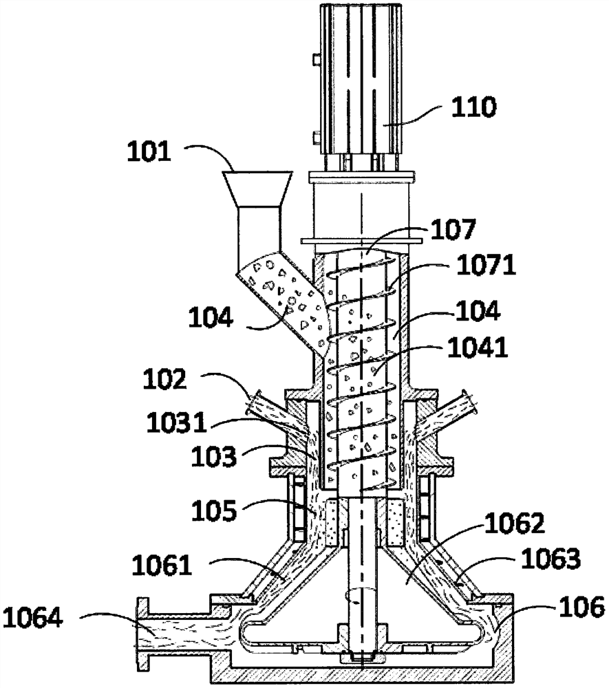
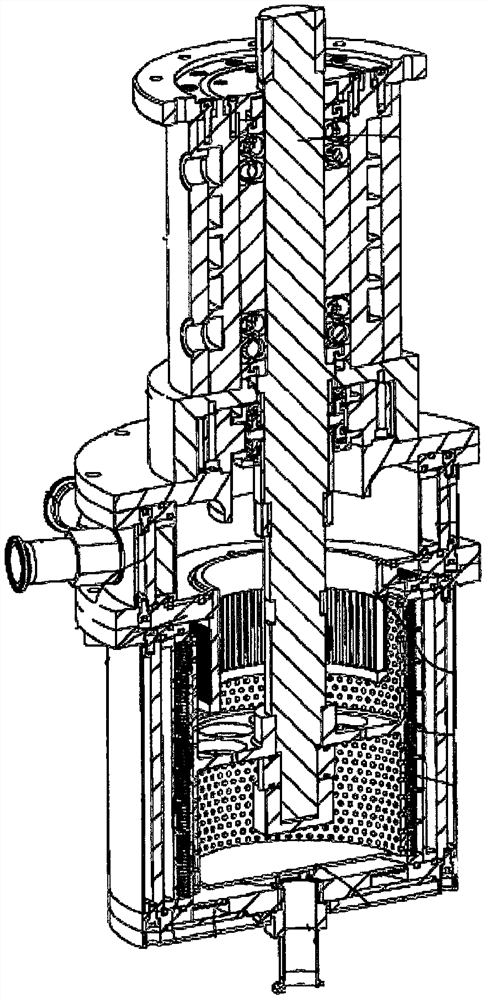
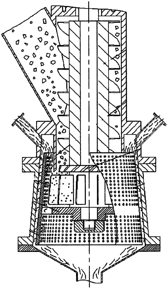
[0040] Such as Figure 10-12 Shown, the...


PUM


Abstract

The invention provides an impeller assembly for solid and liquid mixing equipment, comprising an impeller, the impeller includes a truncated cone-shaped body, a number of mixing blades are formed on the inclined surface of the body from top to bottom, and the impeller assembly also includes an impeller arranged outside the lower part of the body The perforated plate is fixed on the casing of the mixing equipment or the impeller of the impeller assembly, and also includes a number of discharge blades arranged on the outside of the perforated plate in the radial direction. The discharge blades are fixedly connected with the impeller and rotate synchronously with the impeller. . The purpose of the present invention is to provide a kind of mixing equipment which realizes powder infiltration and high-efficiency dispersion, good mixing and dispersing effect, simple structure, low energy consumption, strong processing capacity, and is not easy to block, especially ultrafine powder and mixing equipment. Equipment that mixes liquids to produce highly viscous or highly concentrated liquids.

Description

technical field [0001] The invention relates to the field of solid and liquid mixing equipment, especially the equipment for mixing superfine powder and liquid to generate high-viscosity or high-concentration liquid. The invention also relates to an impeller assembly for the solid and fluid mixing equipment. Background technique [0002] In the industrial field, many liquid raw materials are made by mixing powder and liquid, especially the mixing and dispersing of ultra-fine powder such as nano-scale powder in a small amount of liquid, or mixing and dispersing into a high-viscosity mixed liquid, such as application Slurry in the field of positive and negative electrodes of lithium ion batteries. Generally speaking, the entire mixing process can be divided into three stages, breaking up, infiltration and dispersion. In the stage of breaking up, the powder changes from a large agglomerate to a rough powder state through the stirring of blades and other structures. In the inf...

Claims


Application Information

Patent Timeline
Patent Type & Authority Patents(China)
IPC IPC(8): B01F3/12B01F15/02B01F7/00
CPCB01F23/581B01F23/54B01F23/53B01F27/112B01F35/71775
Inventor 石桥金旭东
Owner SHENZHEN SHANGSHUI INTELLIGENT CO LTD
Why Eureka
Try Eureka