


Quick Research
Generate reliable direction feasibility study reports for your R&D in just a few steps.

Technical Q&A
Discover and master advanced knowledge NOW. Basics, ideas, possibilities, all at once.

Find Solutions
As an expert in R&D theories, this can generate solutions to your technical problems instantly.

Evaluate Feasibility
Analyze your overall solution with one click, know your potential R&D risks in advance.

Monitor Landscape
Get weekly tech updates, stay abreast of the latest tech innovations and key insights.
Rotary camera device
A camera, rotating technology, applied in the field of camera, can solve the problems of inconvenient angle adjustment, limited camera rotation angle, etc.
- Summary
- Abstract
- Description
- Claims
- Application Information
AI Technical Summary
Problems solved by technology
Method used
Image

Examples
Embodiment 1
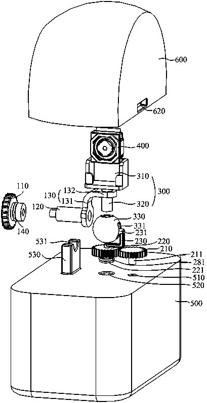
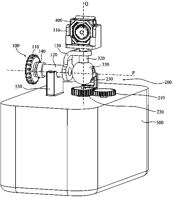
[0039] Embodiment one, with reference to Figure 1 to Figure 4 :
[0040] The horizontal driving assembly 100 includes a first knob 110 and a first shaft 120 fixed to the first knob 110 , the first shaft 120 is arranged horizontally, and a free end of the first shaft 120 is fixed with a support arm 130 . The support arm 130 is an L-shaped structure, including a horizontal section 132 and a vertical section 131 connected to each other. The horizontal section 132 is provided with a first through hole (not shown), and the support rod 320 is vertically passed through the first through hole and rotates relative to the first through hole. Specifically, when the vertical driving assembly 200 acts on the bracket 300 , the support rod 320 can rotate in the first through hole, thereby realizing the rotation of the camera 400 around the vertical axis Q. It should be noted that the supporting rod 320 is loosely fitted with the first through hole, so as to realize the rotational movement...
Embodiment 2
[0052] Embodiment two, refer to Figure 5 to Figure 8 :
[0053] The horizontal driving assembly 100 includes a first knob 110 and a first shaft 120 fixed to the first knob 110 , the first shaft 120 is arranged horizontally, and a free end of the first shaft 120 is fixed with a support arm 130 . The support arm 130 is an inverted U-shaped structure, including opposite vertical sections 131 and a horizontal section 132 disposed between the two vertical sections 131 . The horizontal section 132 is provided with a first through hole (not shown), and the support rod 320 is vertically passed through the first through hole and rotates relative to the first through hole. Specifically, when the vertical driving assembly 200 acts on the bracket 300 , the support rod 320 can rotate in the first through hole, thereby realizing the rotation of the camera 400 around the vertical axis Q.
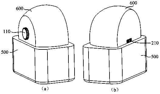
[0054] The first knob 110 is also connected with the first circular hole 610 on the protective cover...
PUM
 Abstract
Description
Claims
Application Information
 - R&D Engineer
- R&D Manager
- IP Professional
- Industry Leading Data Capabilities
- Powerful AI technology
- Patent DNA Extraction
Browse by: Latest US Patents, China's latest patents, Technical Efficacy Thesaurus, Application Domain, Technology Topic, Popular Technical Reports.
© 2024 PatSnap. All rights reserved.Legal|Privacy policy|Modern Slavery Act Transparency Statement|Sitemap|About US| Contact US: help@patsnap.com