
Fabricated tile mounting structure and construction process thereof

An installation structure and prefabricated technology, applied in the direction of building structure, floor, building, etc., can solve the problems of difficult adjustment of tile levelness, high operator requirements, tile cracks, etc., to achieve convenient flatness adjustment, convenient construction, The effect of reducing damage

Active Publication Date: 2019-08-30
浙江矗立建设有限公司
View PDF5 Cites 3 Cited by
  • Summary
  • Abstract
  • Description
  • Claims
  • Application Information

AI Technical Summary

Problems solved by technology

[0004] However, in the actual laying, skilled cement workers need to control the amount and thickness of the coated concrete through experience, and try to ensure that the tiles are close to the level. Otherwise, it is necessary to beat the tiles with a large force, making it difficult to adjust the level of the tiles. It is even easy to cause cracks in the tiles, which leads to relatively high requirements for operators in tile laying, which is more troublesome and needs to be improved

Method used


Image

  • Fabricated tile mounting structure and construction process thereof
  • Fabricated tile mounting structure and construction process thereof
  • Fabricated tile mounting structure and construction process thereof

Examples


Embodiment 1

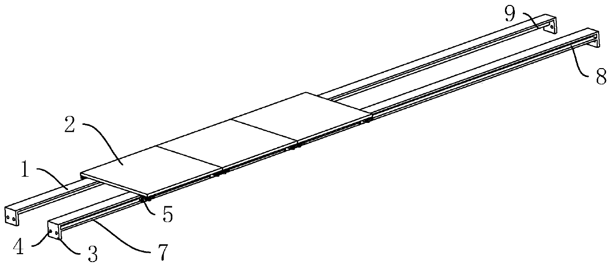
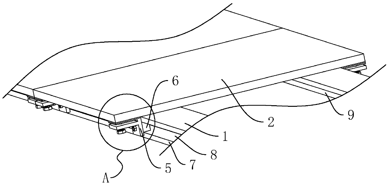
[0047] A prefabricated tile installation structure such as figure 1 As shown, it includes an installation board 1 and a tile board 2 laid on the installation board 1 . There are two mounting plates 1, and the two mounting plates 1 are parallel and symmetrically distributed. The tile boards 2 are arranged along the length direction of the installation board 1 , and each tile board 2 is arranged against the upper end surface of the installation board 1 . Both ends of each mounting plate 1 are provided with flanges 3, the flanges 3 extend in a direction away from the tile plate 2, and the flanges 3 are arranged perpendicular to the mounting plate 1, and the flanges 3 are correspondingly set There are through holes 4 .

[0048] When the installation board 1 is installed, the horizontal line is popped up on the wall through the ink line first, and then the installation board 1 is distributed along the horizontal line. During the installation of the installation board 1, the folde...

Embodiment 2

[0056] A construction technique for a prefabricated ceramic tile installation structure, such as Figure 5 shown, including the following steps:

[0057] S1: Play the horizontal line, through the ink line, pop up the horizontal line at the same height of the wall, usually the horizontal line is 15-25mm higher than the ground.

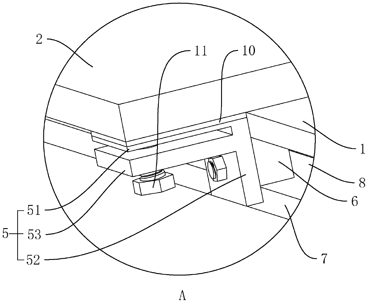
[0058] S2: Fix the installation board, fix the installation board 1 to the wall along the horizontal line through expansion bolts, set the flange 3 of the installation board 1 close to the ground, and set the installation board 1 according to the distance between the fixing seats 5 on the tile board 2 before fixing the installation board 1 The positions of a pair of mounting plates 1 are determined, and the distance between each pair of mounting plates 1 is set corresponding to the side length of the ceramic tile plate 2, so that the tiling of the ceramic tile plate 2 is more convenient. Usually, there is a gap between the installation board 1 and the ...


PUM


Abstract

The invention discloses a fabricated tile mounting structure and relates to the technical field of fabricated decoration. According to key points of the technical scheme, the fabricated tile mountingstructure comprises mounting plates and tile plates laid on the mounting plates, two or more fixing seats are arranged at the ends, close to the mounting plates, of the tile plates and arranged on thetwo sides of the mounting plates correspondingly, limiting blocks are arranged on the fixing seats, and the limiting blocks abut against the end faces, away from the tile plates, of the mounting plates for fixing the tile plates. Through the fabricated mounting structure, tiles are supported by the mounting plates, thus laying operation of the tile plates is convenient, and the effect that tile laying can be completed through a common operator without a skillful cementer is realized accordingly.

Description

technical field [0001] The invention relates to the technical field of prefabricated decoration, more specifically, it relates to a prefabricated ceramic tile installation structure. Background technique [0002] Tiles are a kind of floor decoration materials, also called floor tiles. Ceramic tiles are mostly made of clay and come in various specifications. Ceramic tiles have strong quality, pressure and wear resistance, moisture resistance and decorative functions, and are mostly used for the ground and floor of public buildings and civil buildings. [0003] When laying existing tiles, a layer of concrete that is close to the size of the tiles is applied on the ground, and then the tiles are pasted on the concrete. Before the concrete is cured, the four ends of the tiles are hit with a mallet until the tiles are turned to the level. Ensure the levelness of the tiled floor after laying. [0004] However, in the actual laying, skilled cement workers need to control the amo...

Claims


Application Information

Patent Timeline
Patent Type & Authority Applications(China)
IPC IPC(8): E04F15/08E04F21/22
CPCE04F15/08E04F21/22
Inventor 王良晓
Owner 浙江矗立建设有限公司
Learn More