
Environment control system for environment cabin and environment cabin

A technology for control systems and environmental chambers, applied in control/regulation systems, non-electric variable control, and simultaneous control of multiple variables, etc., can solve problems such as poor control accuracy, numerous pipelines, and low equipment service life.

Active Publication Date: 2019-08-23
BEIJING TECHNOLOGY AND BUSINESS UNIVERSITY
View PDF16 Cites 4 Cited by
  • Summary
  • Abstract
  • Description
  • Claims
  • Application Information

AI Technical Summary

Problems solved by technology

[0005] In order to solve the above-mentioned problems in the prior art, that is, in order to solve the problems of numerous pipelines, poor control accuracy and low service life of equipment in the environmental control system of the traditional environmental chamber, the present invention provides an environmental control system for the environmental chamber, The environmental control system includes an air pump, a first control valve, a liquid storage tank, and a water valve, and the first control valve includes a first inlet connected to the air pump, a first outlet connected to the liquid storage tank, and a first outlet connected to the liquid storage tank. The second outlet connected to the environmental chamber, the water valve is arranged between the liquid storage tank and the environmental chamber; the first control valve is arranged so that the first inlet can be selectively connected to the The first outlet or the second outlet is communicated, so that the air pump is selectively communicated with the liquid storage tank or the environmental chamber; the water valve is arranged to communicate with the liquid storage tank when the air pump is connected open to communicate the liquid storage tank with the environmental chamber, and close to prevent the liquid storage tank from communicating with the environmental chamber when the air pump is in communication with the environmental chamber

Method used

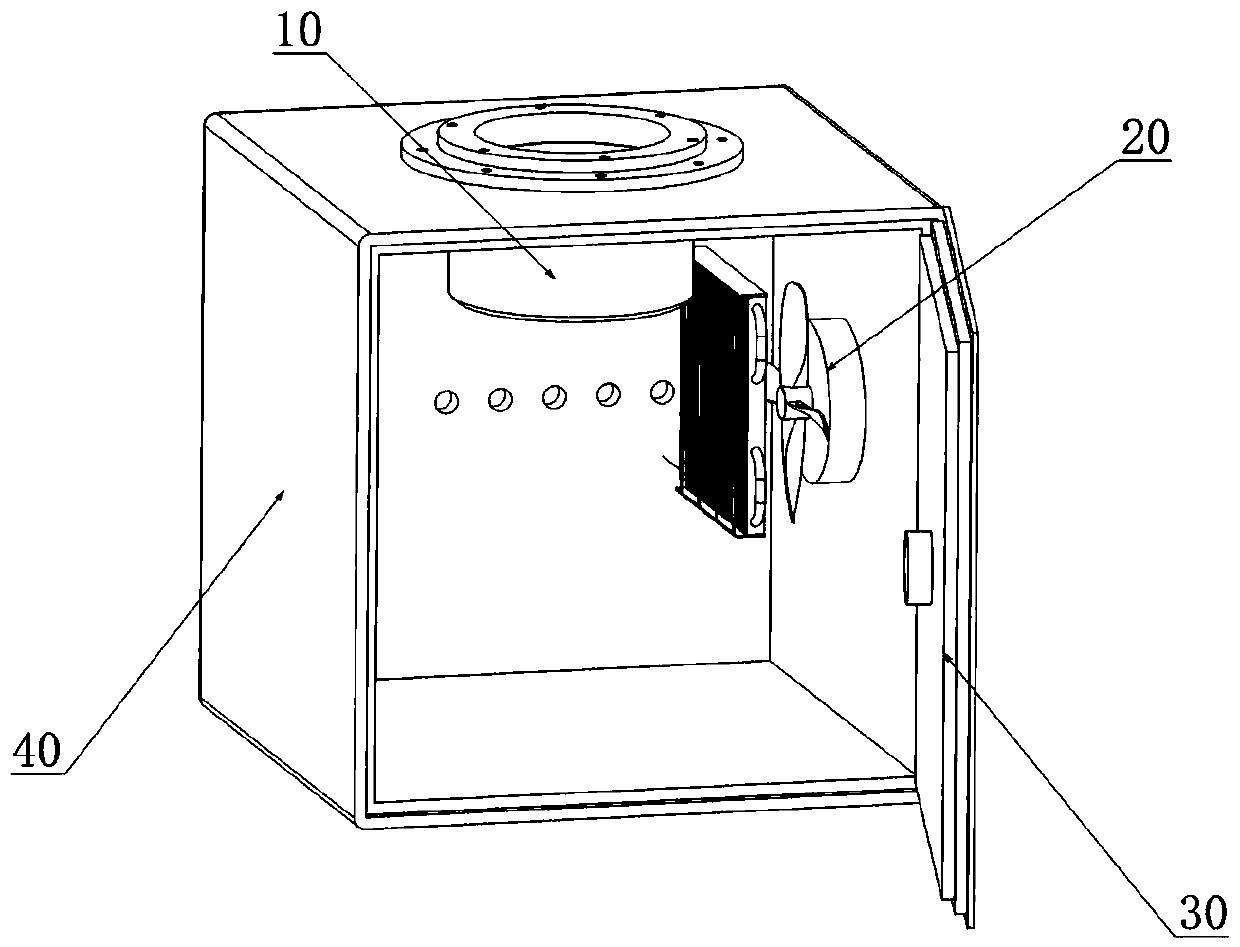
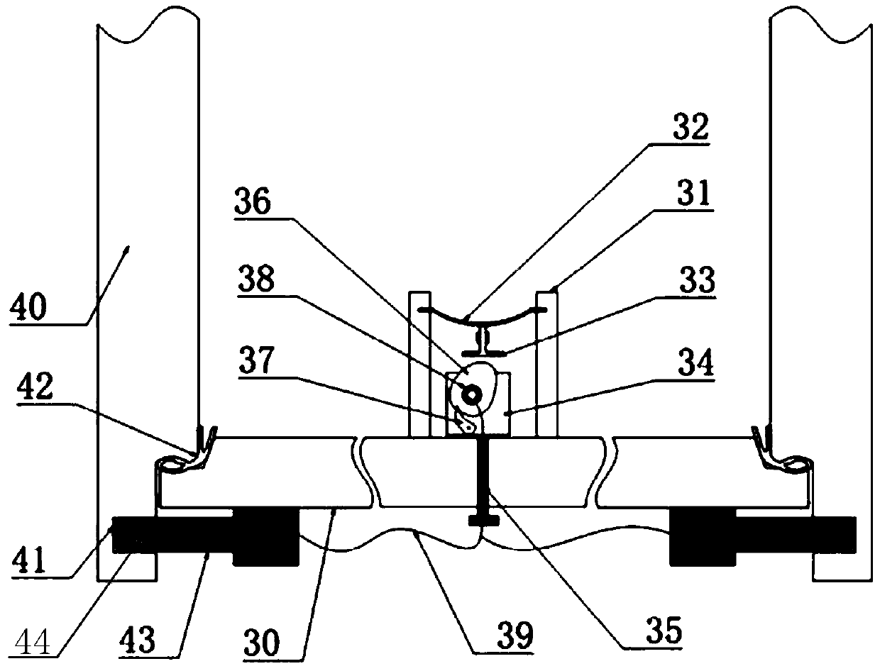
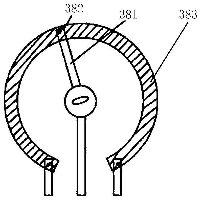

Image

  • Environment control system for environment cabin and environment cabin
  • Environment control system for environment cabin and environment cabin
  • Environment control system for environment cabin and environment cabin

Examples


Embodiment Construction

[0064] Preferred embodiments of the present invention are described below with reference to the accompanying drawings. Those skilled in the art should understand that these embodiments are only used to explain the technical principles of the present invention, and are not intended to limit the protection scope of the present invention. Those skilled in the art can make adjustments as needed so as to adapt to specific applications.

[0065] It should be noted that, in the description of the present invention, terms such as "center", "upper", "lower", "inner", "outer" and other indicated directions or positional relationships are based on the directions or positional relationships shown in the drawings. The positional relationship, which is just for convenience of description, does not indicate or imply that the device or element must have a specific orientation, be constructed and operated in a specific orientation, and thus should not be construed as limiting the present inven...


PUM


Abstract

The invention belongs to the technical field of scientific experiment environment simulation, and particularly provides an environment control system for an environment cabin and an environment cabin,so as to solve the problems of multiple pipelines, poor control precision and low service life for the traditional environment control system for the environment cabin. The environment control systemfor the environment cabin comprises an air pump, a first control valve, a liquid storage tank and a water valve. Through controlling the first control valve, the air pump can be communicated with theenvironment cabin or the liquid storage tank, pressure is thus provided for the environment cabin or water in the liquid storage tank is pressed to the cabin, the pressure and the humidity in the cabin are further adjusted, and further, the environment control system is also provided with an electric heating sheet and a refrigerant pipeline, the temperature in the cabin is adjusted. Through setting a set of control pipeline and a set of refrigerant pipeline, the functions of adjusting the pressure, the temperature and the humidity in the cabin can be realized, the system pipeline is simplified, the control precision is improved, the service life of the device is prolonged, and the cost is thus saved.

Description

technical field [0001] The invention belongs to the technical field of scientific experiment environment simulation, and specifically provides an environment control system for an environment chamber and the environment chamber. Background technique [0002] The environmental simulation chamber is actually a kind of simulation equipment that reasonably simulates the experimental environmental conditions. It is a sealed environmental chamber that can control temperature, humidity and pressure changes in a specific environment. It is mainly used for multi-field scientific experiments. The environmental chamber can simulate low temperature environment, high temperature environment, warm environment, low pressure environment, high pressure environment, etc. The simulated environment parameters can be specifically designed according to the actual needs of users. After the temperature, humidity, and positive and negative pressures in the cabin reach the set conditions, the experim...

Claims


Application Information

Patent Timeline
IPC IPC(8): G05D27/02
CPCG05D27/02
Inventor 高东明
Owner BEIJING TECHNOLOGY AND BUSINESS UNIVERSITY
Learn More