
Channel structure and dust collector

A channel structure and channel technology, used in vacuum cleaners, exhaust diffusion devices, cleaning equipment, etc., can solve problems such as reducing the quality of use of vacuum cleaners, and achieve the effects of weakening high-frequency sound waves, reducing noise, and improving quality of use.

Pending Publication Date: 2019-08-23
NINGBO SAWADIKA ELECTRICAL APPLIANCE
View PDF0 Cites 0 Cited by
  • Summary
  • Abstract
  • Description
  • Claims
  • Application Information

AI Technical Summary

Problems solved by technology

[0004] The motor body can drive the fan to rotate in the working state, so that the air enters the air duct from the air inlet and flows out of the air duct through the air outlet. However, the air will generate noise during the flow in the air duct, which reduces the quality of the vacuum cleaner.

Method used


Image

  • Channel structure and dust collector

Examples


Embodiment Construction

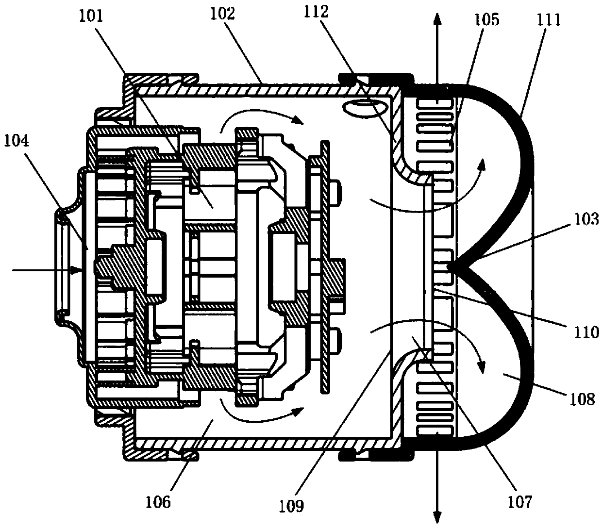
[0015] Please refer to figure 1 , the embodiment of the present invention provides a channel structure, including a fan device 101, a housing 102 and a guide part 103, the housing 102 is provided with an air inlet 104 and an air outlet 105, an air duct is formed in the housing 102, and the air duct Including the first passage 106, the second passage 107 and the third passage 108, the air inlet 104, the first passage 106, the second passage 107, the third passage 108 and the air outlet 105 communicate in sequence, the fan device 101 is arranged in the air duct, and the fan The device 101 can make the air enter the air channel from the air inlet 104 and flow out of the air channel through the first channel 106, the second channel 107, the third channel 108 and the air outlet 105 in turn; the diameter of the second channel 107 is smaller than that of the first Channel 106, to gather the air that flows to the second channel 107 by the first channel 106; The air guide 103 is arrang...


PUM


Abstract

The invention provides a channel structure and a dust collector. The channel structure comprises a fan unit, a shell and a flow guiding part, the shell is provided with an air inlet and an air outlet,an air duct is formed in the shell, the air duct comprises a first channel, a second channel and a third channel, the air inlet, the first channel, the second channel, the third channel and the air outlet sequentially communicate with one another, the fan unit is arranged in the air duct, in a started state, the fan unit enables air to enter the air duct from the air inlet and sequentially pass through the first channel, the second channel, the third channel and the air outlet to flow out of the air duct; the diameter of the second channel is less than that of the first channel so as to converge the air flowing from the first channel to the second channel; and the flow guiding part is arranged in the third channel and used for dispersing the air flowing from the second channel to the third channel, and thus the air can flow in the third channel in different directions. The using quality of the channel structure and the dust collector can be improved.

Description

technical field [0001] The invention relates to motor equipment technology, in particular to a channel structure and a vacuum cleaner. Background technique [0002] With the advancement of science and technology and economic society, vacuum cleaners are widely used in people's daily life. [0003] The existing vacuum cleaner includes a dust collection motor structure, the dust collection motor structure includes an outer shell, an inner shell, a motor body and a fan; the inner shell is arranged in the outer shell, and an accommodation cavity is formed in the inner shell, and the motor body is arranged in the accommodation cavity An air duct is formed between the outer shell and the inner shell, and the fan is located in the air duct and connected to the power output end of the motor body; the outer shell is provided with an air inlet and an air outlet, the air inlet is located at the first end of the outer shell, and the air outlet It is located at the second end of the cas...

Claims


Application Information

Patent Timeline
IPC IPC(8): A47L9/00
CPCA47L9/0081
Inventor 陈锵锵
Owner NINGBO SAWADIKA ELECTRICAL APPLIANCE
Learn More