Piston type pressure gauge and driving device thereof

A technology of piston pressure gauge and driving device, which is applied in the direction of piston fluid pressure measurement, measuring device, and measurement of fluid pressure, etc., which can solve the problem of reducing the absolute pressure measurement efficiency of piston pressure gauge, inability to establish vacuum, and piston pressure Eliminate the scrapped piston rod and piston cylinder, etc., to achieve the effect of vacuuming efficiency and working reliability

Pending Publication Date: 2019-08-20
LIAONING HONGYANHE NUCLEAR POWER
View PDF0 Cites 0 Cited by
  • Summary
  • Abstract
  • Description
  • Claims
  • Application Information

AI Technical Summary

Problems solved by technology

[0003] 1. In the way that the DC motor is placed in the vacuum chamber to drive the piston to rotate, due to the structure of the DC motor, it takes a long time for the gas inside the DC motor to be pumped out. It takes a long time to establish a high vacuum in the vacuum chamber. The vacuum pump works for a long time, which greatly reduces the efficiency of the absolute pressure measurement of the piston pressure gauge;
[0004] 2. The DC motor is placed outside the vacuum chamber, and the motor shaft is extended into the vacuum chamber through the shaft seal, and the piston driving mechanism is driven to rotate the piston. Since the shaft seal is a dynamic seal, the seal will be damaged as the use time increases. The parts are easy to wear, the sealing effect is reduced, and even the shaft seal fails completely, and a vacuum cannot be established in the vacuum chamber at the reference end of the piston
The above two methods also directly apply the output torque of the DC motor to the piston. When the piston cannot rotate well due to various reasons and needs to be cleaned, the large torque of the DC motor may damage the piston, making the piston of the piston gauge Rod and piston cylinder scrapped

Method used


Image

  • Piston type pressure gauge and driving device thereof
  • Piston type pressure gauge and driving device thereof
  • Piston type pressure gauge and driving device thereof

Examples


Embodiment Construction

[0021] The technical solutions in the embodiments of the present invention will be clearly and completely described below in conjunction with the accompanying drawings in the embodiments of the present invention. Obviously, the described embodiments are only a part of the embodiments of the present invention, rather than all the embodiments. Based on the embodiments of the present invention, all other embodiments obtained by those of ordinary skill in the art without creative work shall fall within the protection scope of the present invention.

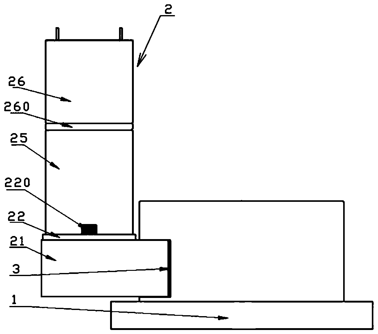
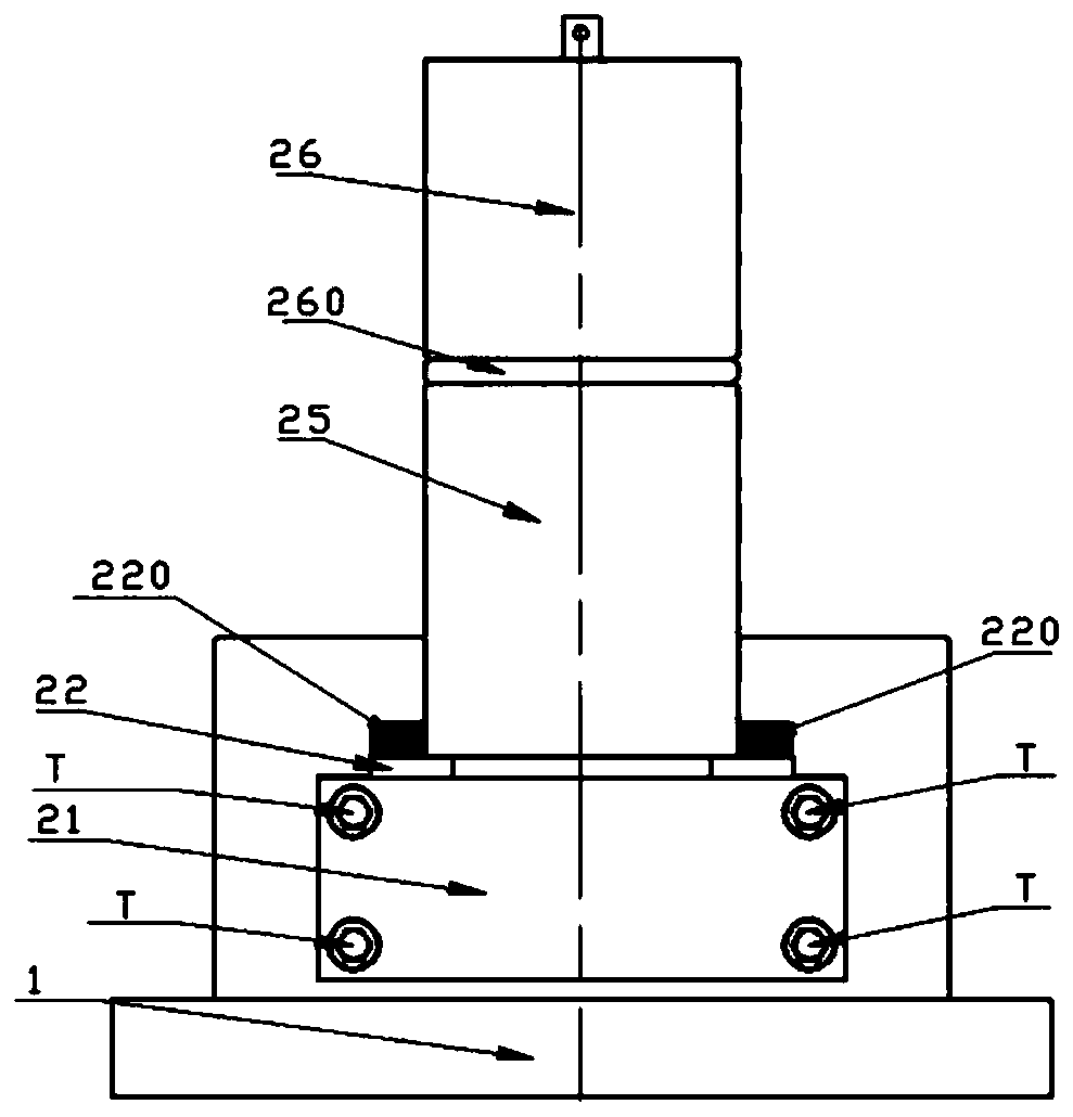
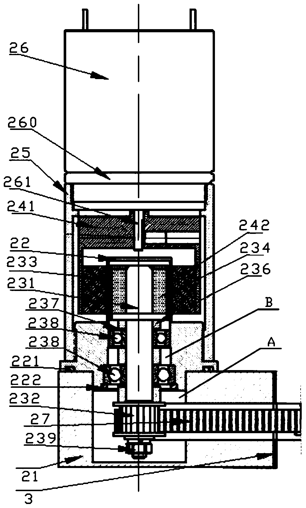
[0022] See also Figure 1-Figure 3 Shown is the first embodiment of the absolute pressure piston pressure gauge of the present invention.

[0023] The absolute pressure piston pressure gauge in this embodiment includes a piston rotation driving body 1 and a driving device 2 for driving the piston rotation driving body 1. A rubber gasket 3 is placed between the driving device 2 and the piston rotation driving body 1. The driving device 2 ...


PUM


Abstract

The invention discloses a driving device for a piston type pressure gauge. The driving device comprises a driving fixing component, an isolation cover, a concentric cylinder and a driving motor; a first inner cavity is formed in the driving fixing component; the isolation cover is fixedly connected to the driving fixing component; a second inner cavity is formed in the isolation cover; a magnetictransmission driven assembly is fastened in the second inner cavity; the magnetic transmission driven assembly comprises a driven shaft and a main synchronous belt wheel connected to the driven shaft;a magnetic transmission driving assembly is arranged on the outer side of the isolation cover; the concentric cylinder is fastened onto the isolation cover; the driving motor is fastened onto the concentric cylinder; the driving motor comprises a rotating shaft; and the magnetic transmission driving assembly is fixedly connected with the rotating shaft. The invention further discloses an absolutepressure piston type pressure gauge. With the piston type pressure gauge and the driving device thereof provided by the invention adopted, a piston and a piston cylinder are effectively prevented from being damaged by overlarge torques; and the vacuumizing efficiency and working reliability of the absolute pressure measurement piston type pressure gauge are realized.

Description

Technical field [0001] The invention relates to the field of nuclear power measurement, in particular to a piston pressure gauge and a driving device thereof. Background technique [0002] The piston pressure gauge for absolute pressure measurement in the prior art mainly has the following two ways to drive the piston to rotate. One is to directly install a DC motor in the vacuum chamber, and the DC motor directly drives the piston drive mechanism to dial the piston. Rotation; one is to install the DC motor outside the vacuum chamber, the DC motor extends the motor shaft into the vacuum chamber through the shaft seal, and drives the piston drive mechanism to dial the piston to rotate. Due to the unreasonable structural design of the above-mentioned absolute pressure piston pressure gauge, the following technical problems mainly exist: [0003] 1. In the way that the DC motor is placed in the vacuum chamber to drive the piston to rotate, due to the structure of the DC motor, the ga...

Claims


Application Information

Patent Timeline
Patent Type & Authority Applications(China)
IPC IPC(8): G01L7/16G01L27/00
CPCG01L7/163G01L27/00
Inventor 郭雪锋胡汝平
Owner LIAONING HONGYANHE NUCLEAR POWER
Why Eureka
Try Eureka