Gas flow sputtering device, target for gas flow sputtering, and manufacturing method of sputtering target raw material
A technology of airflow sputtering and manufacturing method, which is applied in the directions of sputtering coating, sputtering coating, record carrier manufacturing, etc., can solve the problem of difficult to completely eliminate particles, etc., and achieve the effect of low cost and high production efficiency
Active Publication Date: 2021-12-07
JX NIPPON MINING & METALS CO LTD
View PDF9 Cites 0 Cited by
- Summary
- Abstract
- Description
- Claims
- Application Information
AI Technical Summary
Problems solved by technology
However, in the current mechanical pulverization and mixing method, there is a physical limit to the mi
Method used
View moreImage
Smart ImageViewing Examples
Examples
 PUM
| Property | Measurement | Unit |
|---|---|---|
| Power density | aaaaa | aaaaa |
| Power density | aaaaa | aaaaa |
| Power density | aaaaa | aaaaa |
Abstract
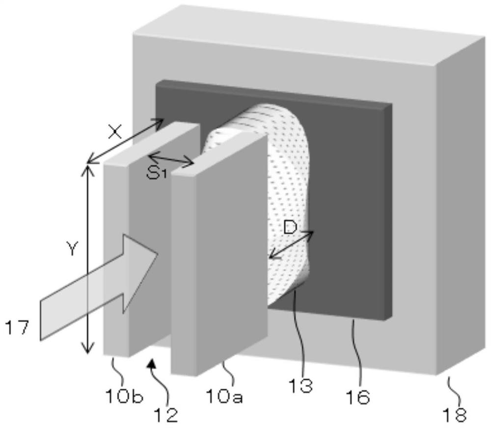
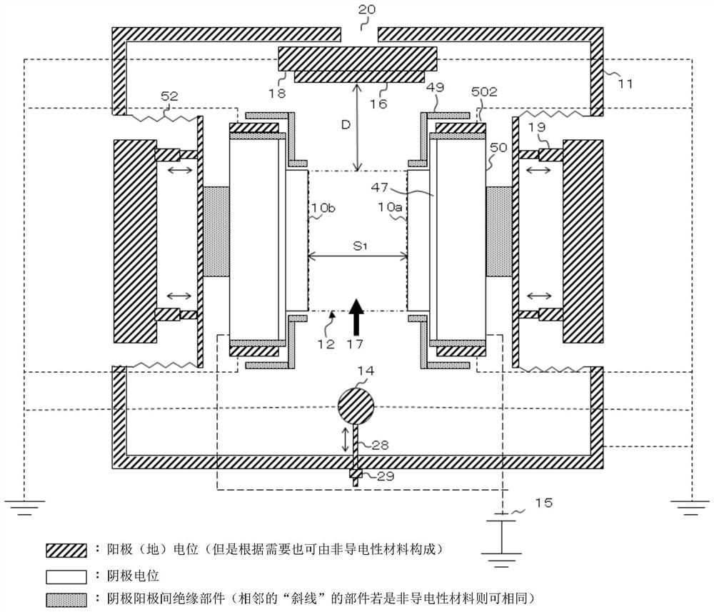
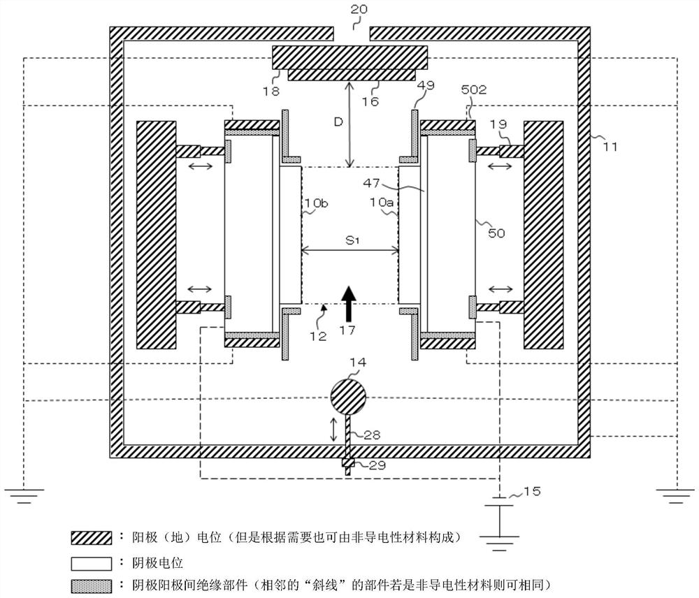
The invention provides a gas flow sputtering device suitable for manufacturing sputtering target raw materials stably and at a high sputtering rate for a long time. The gas flow sputtering device is provided with: a sputtering chamber, the inside of which can be vacuumed; a pair of flat targets arranged in the sputtering chamber with their sputtering faces facing each other at intervals; one or more gas an exhaust port for supplying sputtering gas between the pair of flat targets; an exhaust port for exhausting the sputtering gas; A space between the flat targets is disposed on a side opposite to the gas discharge port; and an interval adjustment mechanism capable of adjusting an interval between the pair of flat targets.
Description
technical field [0001] The present invention relates to a gas flow sputtering device, a target for gas flow sputtering and a method for manufacturing raw materials for the sputtering target. Background technique [0002] In the field of magnetic recording typified by hard disk drives, materials based on ferromagnetic metals Co, Fe, or Ni are used as materials for magnetic thin films responsible for recording. For example, a Co—Cr-based or Co—Cr—Pt-based ferromagnetic alloy containing Co as a main component is used for the recording layer of a hard disk employing an in-plane magnetic recording method. In the recording layer of the hard disk using the perpendicular magnetic recording method that has been put into practical use in recent years, a composite material in which nonmagnetic particles such as oxides and carbon are dispersed in a Co-Cr-Pt-based ferromagnetic alloy mainly composed of Co is used. Material. [0003] From the viewpoint of high productivity, sputtering t...
Claims
Login to View More Application Information
Patent Timeline
 IPC IPC(8): C23C14/34G11B5/851
CPCC23C14/34G11B5/851
Inventor 小庄孝志高见英生中村祐一郎武智幹雄三上智广
Owner JX NIPPON MINING & METALS CO LTD
Features
- R&D
- Intellectual Property
- Life Sciences
- Materials
- Tech Scout
- Unparalleled Data Quality
- Higher Quality Content
- 60% Fewer Hallucinations
Learn More Browse by: Latest US Patents, China's latest patents, Technical Efficacy Thesaurus, Application Domain, Technology Topic, Popular Technical Reports.
© 2025 PatSnap. All rights reserved.Legal|Privacy policy|Modern Slavery Act Transparency Statement|Sitemap|About US| Contact US: help@patsnap.com


