Protection configuration method suitable for multiport flexible transformer substation

A multi-terminal flexible and protective configuration technology, applied in emergency protection circuit devices, electrical components, etc., can solve the problems of current transformer lines being unable to protect, unable to cover the full length of the line, etc., to reduce the phenomenon of abandoned light and wind, and to protect the action quickly. Effective, easy-to-engineer results

Active Publication Date: 2019-07-30
STATE GRID JIBEI ELECTRIC POWER COMPANY +2
View PDF7 Cites 6 Cited by
  • Summary
  • Abstract
  • Description
  • Claims
  • Application Information

AI Technical Summary

Problems solved by technology

The DC line part of the flexible DC distribution network has hundreds of kilometers and only two AC input and output ports, while the multi-terminal flexible substation has multiple ports and the line length is only a few kilometers. These characteristics make the protection of the multi-terminal flexible substation impossible to copy Flexible DC distribution network, traveling wave protection is no longer suitable for multi-terminal interfaces
According to the characteristics of flexible substations, longitudinal differential protection can protect multi-terminal lines, but this cannot cover the entire length of the line, and cannot protect lines other than current transformers

Method used


Image

  • Protection configuration method suitable for multiport flexible transformer substation
  • Protection configuration method suitable for multiport flexible transformer substation
  • Protection configuration method suitable for multiport flexible transformer substation

Examples


Embodiment Construction

[0034] The present invention will be further described in detail below in conjunction with the accompanying drawings.

[0035] The present invention is applicable to the protection configuration method of the multi-terminal flexible substation, including the following aspects:

[0036] 1. Divide the multi-terminal flexible substation into AC pre-protection area, DC pre-protection area, DAB protection area, DC post-protection area and AC post-protection area, as follows:

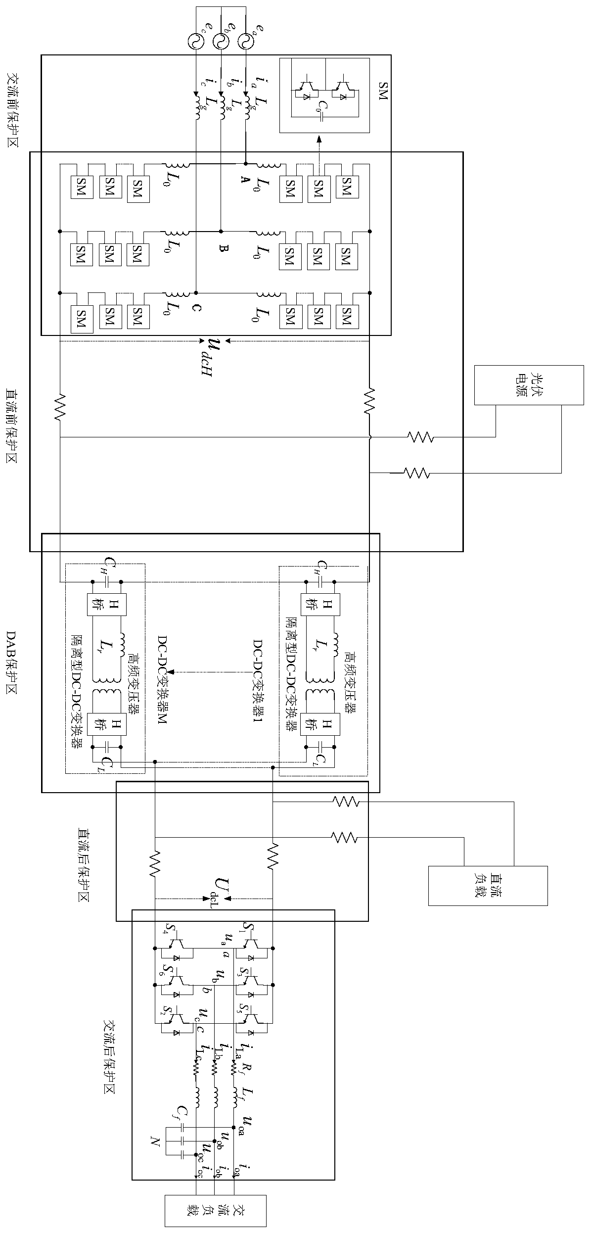
[0037] Such as figure 1 As shown, the multi-terminal flexible substation is divided into five protection areas: AC front protection area, DC front protection area, DAB protection area, DC rear protection area and AC rear protection area. stability.

[0038] Further, in the multi-terminal flexible substation, the interface mode adopts a multi-terminal interface mode, and the system structure adopts a three-level system structure;

[0039] The multi-terminal interface mode includes the DC power input line an...


PUM


Abstract

The invention discloses a protection configuration method suitable for a multiport flexible transformer substation. The method comprises the following steps: dividing the multiport flexible transformer substation into an AC front protection area, a DC front protection area, a DAB protection area, a DC rear protection area and an AC rear protection area, wherein a protection range of the AC front protection area ranges from an AC power incoming line to a modularized multi-level current converter outgoing line, the protection range of the DC front protection area ranges from the modularized multi-level current converter outgoing line to a DAB incoming line, the protection range of the DAB protection area ranges from the DAB incoming line to a DAB outgoing line, the protection range of the DCrear protection area ranges from the DAB outgoing line to an inverter incoming line, and the protection range of the AC rear protection area ranges from the inverter outgoing line to an AC load incoming line; and aiming at different protection areas, protecting the multiport flexible transformer substation through different protection strategies. With the method provided by the invention, an AC power can be switched in freely, occurrence of a phenomenon of discarding optical energy and wind energy when new energy, such as wind electricity and optical electricity, is connected to a grid is reduced, moreover, the multiport flexible transformer substation is protected completely, and the method can flexibly be adaptive to various power electronic device conditions of the multiport flexible transformer substation.

Description

technical field [0001] The invention relates to the technical field of electric power system relay protection, in particular to a protection configuration method suitable for multi-terminal flexible substations. Background technique [0002] With the rapid development of new energy technologies, large-scale wind power and photovoltaic grid-connected operation. Compared with the original method of inverting new energy and connecting it to the grid, the multi-terminal flexible substation can directly integrate the new energy into the DC grid after transformation, saving the cost of building an inverter station. The DC line part of the flexible DC distribution network has hundreds of kilometers and only two AC input and output ports, while the multi-terminal flexible substation has multiple ports and the line length is only a few kilometers. These characteristics make the protection of the multi-terminal flexible substation impossible to copy For flexible DC distribution netwo...

Claims


Application Information

Patent Timeline
Patent Type & Authority Applications(China)
IPC IPC(8): H02H7/22H02H7/26
CPCH02H7/22H02H7/268
Inventor 梁东覃朝云宗瑾张建
Owner STATE GRID JIBEI ELECTRIC POWER COMPANY
Why Eureka
Try Eureka