Continuous bottle cap marking production line

A production line and bottle cap technology, applied in auxiliary devices, laser welding equipment, auxiliary welding equipment, etc., can solve the problems of inaccurate sensor detection data, misoperation, and difficulty in avoiding interference, and achieve better results.

Active Publication Date: 2019-07-23
DEMARK (CHANGXING) INJECTION SYST CO LTD
View PDF7 Cites 0 Cited by
  • Summary
  • Abstract
  • Description
  • Claims
  • Application Information

AI Technical Summary

Problems solved by technology

[0004] There are many deficiencies in the above mechanism. When performing laser marking operations, the position of the bottle cap is judged by the sensor. On the one hand, the sensor detection data is not accurate enough; on the other hand, it is difficult to avoid some interference, which may easily lead to misoperation

Method used


Image

  • Continuous bottle cap marking production line
  • Continuous bottle cap marking production line
  • Continuous bottle cap marking production line

Examples


Embodiment 1

[0062] Embodiments of the present invention are described in detail below, examples of which are shown in the drawings, wherein the same or similar reference numerals designate the same or similar elements or elements having the same or similar functions throughout. The embodiments described below by referring to the figures are exemplary and are intended to explain the present invention and should not be construed as limiting the present invention.

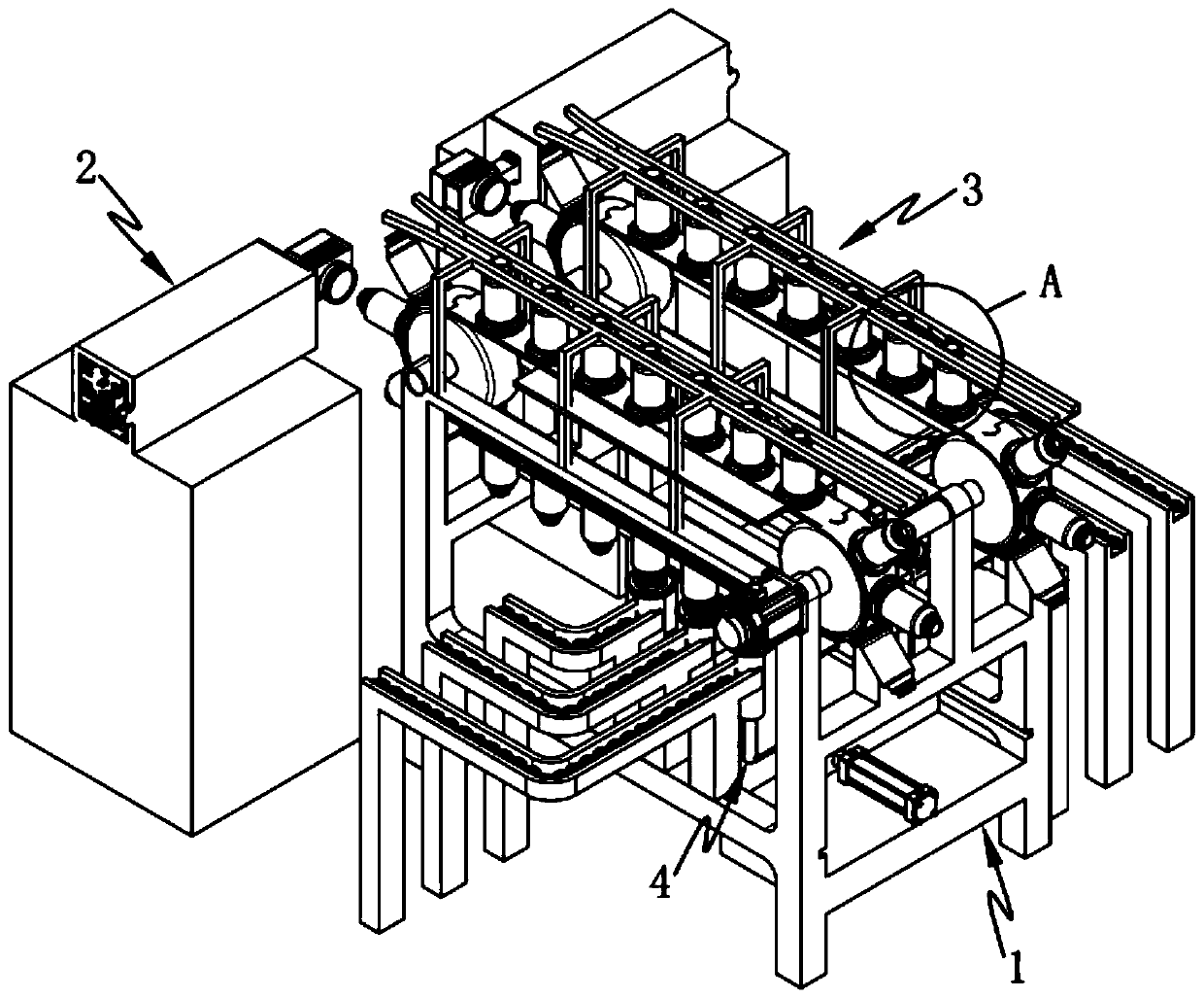
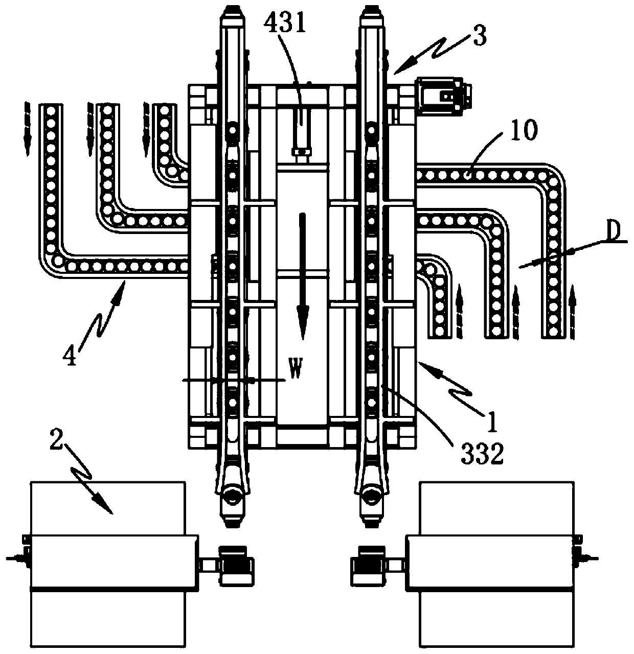
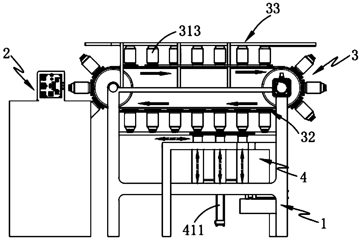
[0063] Such as figure 1 , 2 , 3 and 4, a continuous bottle cap marking production line includes a bracket 1 and a marking device 2, and also includes:

[0064] The bottle cap transfer device 3, the bottle cap transfer device 3 is arranged on the support 1, the bottle cap transfer device 3 includes a rotary assembly 31 which is rotatably arranged on the support 1, and a rotary assembly 31 which is arranged below the rotary assembly 31. The feeding limit assembly 32 and the output assembly 33 arranged above the rotary assembly 31...


PUM


Abstract

The invention provides a continuous bottle cap marking production line. The continuous bottle cap marking production line comprises a support, a marking device, a bottle cap transferring device and afeeding device, wherein the bottle cap transferring device comprises a rotary assembly, a feeding limiting assembly and an output assembly. The bottle cap transferring device and the feeding device are arranged, the feeding device pushes bottle caps needing to be marked with codes upwards, screws the bottle caps to a bottle cap limiting part on the bottle cap transferring device, and keeps the state of tracking the rotating direction of the bottle cap transferring device in the upward pushing process; the bottle cap transferring device sequentially drives the bottle caps which are uniformly distributed at intervals to the marking device for marking in the rotating motion process, and automatic outward discharge of the bottle caps after marking can be realized in the process that the bottlecap transferring device continues rotating; the technical problems that in the prior art, time and labor are wasted due to the fact that the bottle caps need to be linearly arranged by people beforelaser marking is carried out can be solved; and meanwhile, the technical problems of large interference and large error during laser marking operation are solved.

Description

technical field [0001] The invention relates to the technical field of bottle cap processing, in particular to a continuous bottle cap marking production line. Background technique [0002] At present, in the bottle cap production industry, more and more bottle caps use laser marking barcodes, QR codes, patterns, text, numbers, letters and other content on the surface or inside. In the marking process, a set of bottle cap auxiliary equipment and one or two sets of laser marking equipment are usually used for online marking. Moreover, the domestic bottle cap manufacturing industry has adopted a dynamic marking system when marking bottle caps, which can monitor the position of the bottle cap in real time and control the laser to mark when it reaches the designated position, but there are still low efficiency , For example, currently in the field of online laser marking, one laser marking machine (single-head laser) or two laser marking machines (double-head laser) are used fo...

Claims


Application Information

Patent Timeline
Patent Type & Authority Applications(China)
IPC IPC(8): B23K26/362B23K26/70B23K37/047
CPCB23K26/362B23K37/047B23K26/702
Inventor 王巍植
Owner DEMARK (CHANGXING) INJECTION SYST CO LTD
Why Eureka
Try Eureka