
Energy-saving indoor lighting control method and system

An indoor lighting and control method technology, applied in the field of energy-saving indoor lighting control methods and systems, can solve the problems of voice-activated switch lighting control, sound interference, complex personnel environment, etc., and achieve the effects of accurate human behavior monitoring and accurate and effective switch control.

Pending Publication Date: 2019-07-09
SUZHOU UNIV OF SCI & TECH
View PDF5 Cites 1 Cited by
  • Summary
  • Abstract
  • Description
  • Claims
  • Application Information

AI Technical Summary

Problems solved by technology

Among them, the energy-saving lighting control method has always been one of the focuses in the field of building intelligence. The most typical energy-saving lighting control method is the voice-activated switch technology, which controls the on and off of lights by collecting people's voices. It has been widely used in residential areas, especially the control of single lamps by voice-activated switches, but voice-activated switches have not been well used in offices, classrooms or libraries. There are two main reasons: one is that these public places have a large area, There are multiple lights at the same time, and it is impossible to set a suitable voice-activated switch to control multiple lights; second, the environment of these public places is complex and the mobility is large, so that the voice-activated switch cannot perform a good lighting control function, and various sounds from the outside will cause greater disturbance
Therefore, for public places such as offices, classrooms, and libraries, it is unrealistic to achieve good energy saving goals through voice-activated switches.

Method used


Image

  • Energy-saving indoor lighting control method and system
  • Energy-saving indoor lighting control method and system
  • Energy-saving indoor lighting control method and system

Examples


Embodiment Construction

[0018] In order to make the object, technical solution and beneficial effects of the present invention more clear, the present invention will be further described in detail below in conjunction with the accompanying drawings and embodiments. It should be understood that the specific embodiments described here are only used to explain the present invention, not to limit the present invention. Based on the embodiments of the present invention, all other embodiments obtained by persons of ordinary skill in the art without making creative efforts belong to the protection scope of the present invention.

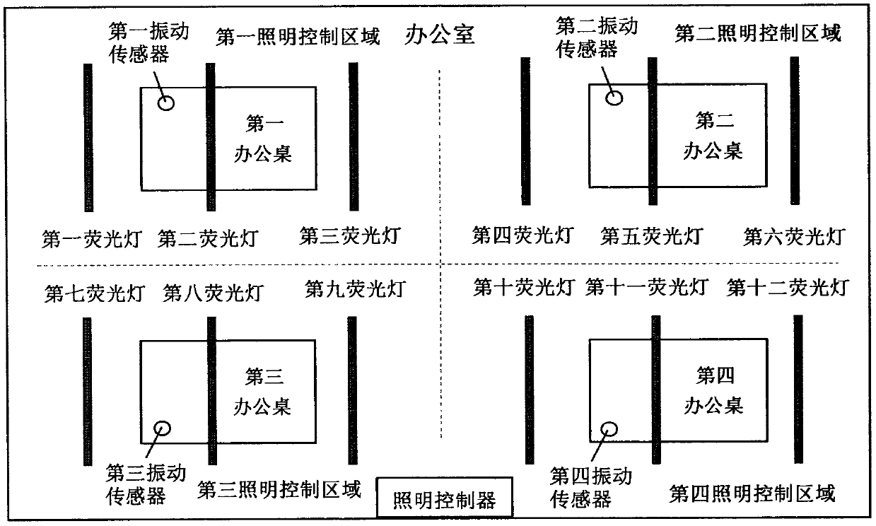
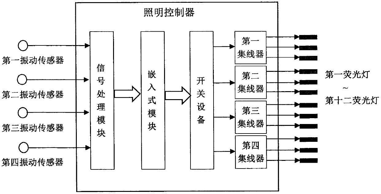
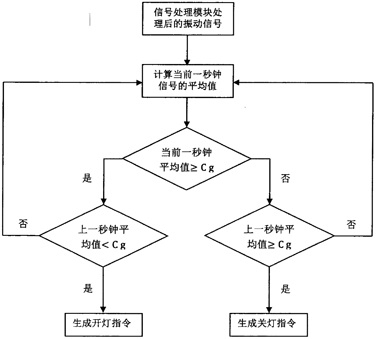
[0019] In this embodiment, an office with 4 desks regularly placed on the ground and 12 fluorescent lamps installed on the ceiling is taken as an example to illustrate the implementation process and working principle of the invention. figure 1 It shows an example diagram of the energy-saving indoor lighting control method in the office, figure 2 It is a structural diagram of an ...


PUM


Abstract

The invention discloses an energy-saving indoor lighting control method and system. The system comprises vibration sensors, a lighting controller and lamps. The lighting controller comprises a signalprocessing module, an embedded module, hubs and a piece of switchgear. The lighting control method based on the modules and equipment is as follows: one vibration sensor is installed on the desktop ofeach energy-saving area in the room to identify whether there is anyone around; the vibration signals collected by each vibration sensor are transmitted to the lighting controller; the signal processing module and the embedded module in the lighting controller process and analyze each input vibration signal, and output a lamp turning-on-off instruction to the switchgear according to a lamp control strategy; and the switchgear controls lamps connected to each hub, wherein the lamps connected to each hub belong to the same lighting control area. The indoor lighting lamps are controlled based onthe vibration signals of the vibration sensors, and thus, the goal of lighting energy saving is achieved.

Description

technical field [0001] The invention relates to the technical field of lighting energy saving, in particular to an energy-saving indoor lighting control method and system. Background technique [0002] In the past two decades, lighting energy saving has received great attention, and many lighting energy-saving technologies have been developed, including energy-saving lighting sources and energy-saving lamps, and the development of energy-saving lighting control methods. Among them, the energy-saving lighting control method has always been one of the focuses in the field of building intelligence. The most typical energy-saving lighting control method is the voice-activated switch technology, which controls the on and off of lights by collecting people's voices. It has been widely used in residential areas, especially the control of single lamps by voice-activated switches, but voice-activated switches have not been well used in offices, classrooms or libraries. There are two ...

Claims


Application Information

Patent Timeline
Patent Type & Authority Applications(China)
IPC IPC(8): H05B37/02
CPCH05B47/105Y02B20/40
Inventor 李长宁朱学莉胡惠轶
Owner SUZHOU UNIV OF SCI & TECH
Learn More