Eureka AIR delivers breakthrough ideas for toughest innovation challenges, trusted by R&D personnel around the world.

Surround-view wide-angle athermal lens and automobile panoramic view system

A wide-angle and lens technology, applied in the field of optical lenses, can solve problems such as insufficient field of view, poor temperature compensation performance, and large distortion of all-glass structures, and achieve the effects of reducing production costs, improving imaging quality, and shortening the total optical length

Pending Publication Date: 2019-07-05
SIRTEC INT SUZHOU
View PDF0 Cites 3 Cited by
  • Summary
  • Abstract
  • Description
  • Claims
  • Application Information

AI Technical Summary

Problems solved by technology

[0004] At present, the main ordinary wide-angle lenses in the camera lens market generally adopt an all-glass structure with excessive distortion, or only the first glass lens and the rest are all made of plastic materials, and the temperature compensation performance is not good, which cannot meet the high-end automotive market applications.
There are many defects in the existing surround view lenses on the market, such as insufficient field of view, excessive distortion, high production cost, poor imaging quality, poor temperature compensation characteristics, complex structure, etc., which make it difficult to meet user needs

Method used


Image

  • Surround-view wide-angle athermal lens and automobile panoramic view system
  • Surround-view wide-angle athermal lens and automobile panoramic view system
  • Surround-view wide-angle athermal lens and automobile panoramic view system

Examples


Embodiment Construction

[0038] The following will clearly and completely describe the technical solutions in the embodiments of the present invention with reference to the accompanying drawings in the embodiments of the present invention. Obviously, the described embodiments are only some, not all, embodiments of the present invention. Based on the embodiments of the present invention, all other embodiments obtained by persons of ordinary skill in the art without making creative efforts belong to the protection scope of the present invention.

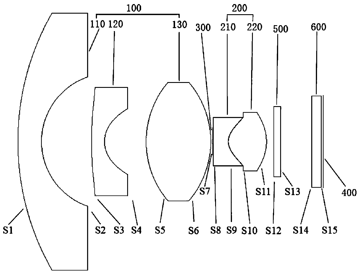
[0039] See figure 1 , the present invention provides a wide-angle surround-view athermalized lens, comprising a front lens group 100, a diaphragm 300, a rear lens group 200, and an imaging surface 400 arranged sequentially from the object side to the image side; figure 1 In , the object space is located on the left side of the figure, and the image space is located on the right side of the figure, and from the left side to the right side of the figure is from ...


PUM

PropertyMeasurementUnit
viewing angleaaaaaaaaaa
Abbe numberaaaaaaaaaa
refractive indexaaaaaaaaaa

Abstract

The invention provides a surround-view wide-angle athermal lens; the surround-view wide-angle athermal lens is high in resolving power, small in optical distortion and capable of reducing the size ofthe lens, the comprehensive performance of the lens is improved, and the cost is saved; the athermal lens comprises a first lens, a second lens, a third lens, a fourth lens and a fifth lens, which aresequentially arranged from an object space to an image space; the first lens is provided with negative focal power, the object surface side of the first lens is a convex surface, and the image surface side of the first lens is a concave surface; the second lens is provided with negative focal power, the object surface side of the second lens is a convex surface, and the image surface side of thesecond lens is a concave surface; the third lens is provided with positive focal power, the object surface side of the third lens is a convex surface, and the image surface side of the third lens is aconvex surface; the fourth lens is provided with negative focal power, the object surface side of the fourth lens is a convex surface, and the image surface side of the third lens is a concave surface; the fifth lens is provided with positive focal power, the object surface side of the fifth lens is a convex surface, and the image surface side of the third lens is a convex surface, wherein the fourth lens and the fifth lens are in optical cementation; and meanwhile, the invention further provides an automobile panoramic view system comprising the surround-view wide-angle athermal lens.

Description

technical field [0001] The invention relates to the technical field of optical lenses, in particular to a surround-view wide-angle athermalization lens and an automobile panoramic surround-view system. Background technique [0002] With the rapid development of image and computer vision technology, more and more technologies are applied to the field of automotive electronics. The traditional image-based reversing camera system only installs a camera at the rear of the car, which can only cover a limited area around the rear of the car. The blind spots around the vehicle and the front of the vehicle undoubtedly increase the hidden dangers of safe driving, and collisions and scratches are prone to occur in narrow and congested urban areas and parking lots. In order to expand the driver's field of vision, it is necessary to be able to perceive the 360° all-round environment, which requires the mutual cooperation of multiple visual sensors and then through video synthesis proces...

Claims


Application Information

Patent Timeline
Patent Type & Authority Applications(China)
IPC IPC(8): G02B13/06G02B13/18G02B1/00G02B1/04
CPCG02B13/06G02B13/18G02B1/00G02B1/041
Inventor 吴喆明耿永飞杨井留马少婷
Owner SIRTEC INT SUZHOU
Why Eureka
Eureka Blog
Learn More