Locomotive unit brake demounting, mounting and transferring mechanism

A technology for brakes and locomotives, applied in the direction of transportation of passenger cars, hoisting devices, transportation and packaging, etc., can solve the problems of waste of personnel in the maintenance warehouse, physical injury of operators, and narrow operating space, and achieves reduction of labor intensity, improvement of work efficiency, Easy-to-use effects

Pending Publication Date: 2019-07-05
TANGSHAN BAICHUAN INTELLIGENT MACHINE
View PDF0 Cites 2 Cited by
  • Summary
  • Abstract
  • Description
  • Claims
  • Application Information

AI Technical Summary

Problems solved by technology

[0002] Harmony high-power locomotives are the main equipment for freight operations in my country's rail transportation system. The unit brake equipment on it, although the locomotive models are different, its size and mechanism have no major changes, the weight is between 150 and 80kg, and the unit brake volume Smaller, but because it is installed on the side of the wheel set, major locomotive maintenance bases need multiple operators to send various cumbersome procedures to disassemble it without dismantling the locomotive bogie as a whole, and it is difficult to install , the key to the whole operation lies in the fixing and transfer of the unit brake equipment. The whole operation space is narrow and the maintenance is unchanged. It is easy to cause physical injury to the operator, and the continuous work for a long time will easily cause the staff to be fatigued and weak. At the same time, due to the large number of people required for the work, it will cause waste to the personnel in the overall maintenance warehouse and affect other work

Method used


Image

  • Locomotive unit brake demounting, mounting and transferring mechanism
  • Locomotive unit brake demounting, mounting and transferring mechanism
  • Locomotive unit brake demounting, mounting and transferring mechanism

Examples


Embodiment Construction

[0017] The present invention will be further described below in conjunction with the examples, the purpose is only to better understand the contents of the present invention, therefore, the examples given do not limit the protection scope of the present invention.

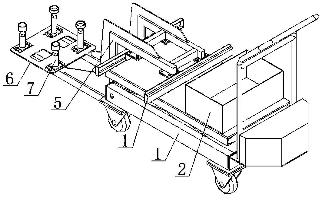
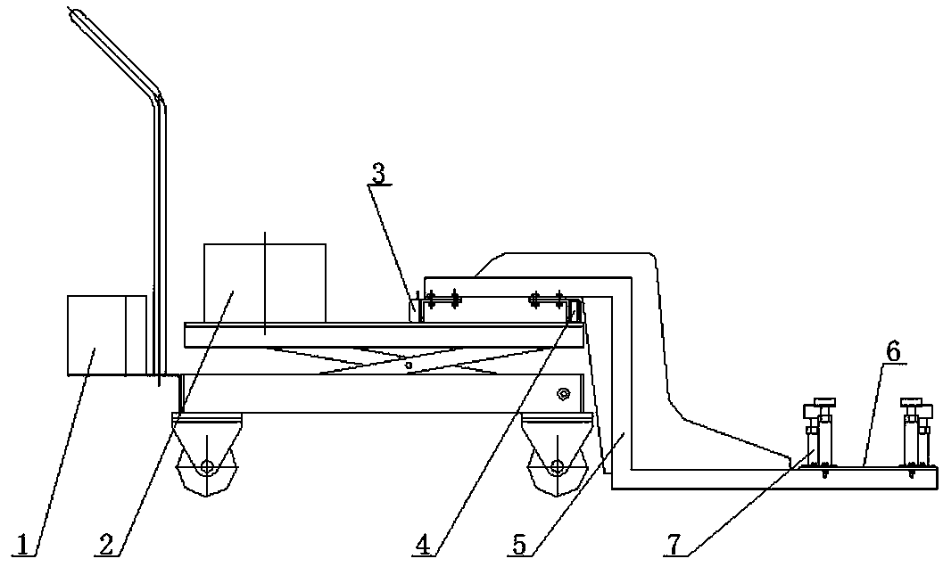
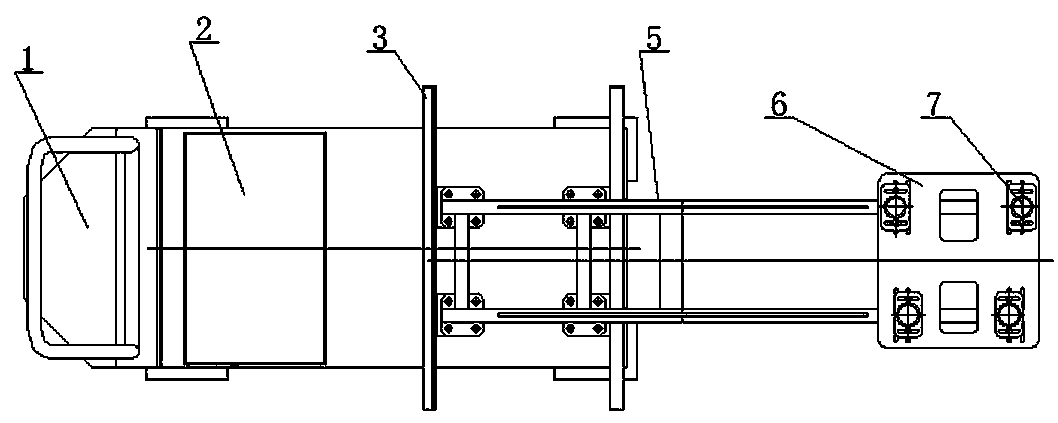
[0018] see figure 1 , figure 2 , image 3 , a locomotive unit brake removal, installation and transfer mechanism, including an electric lifting flat car 1, a sliding track 3, a roller bearing 4 cooperating with the sliding track 3, a Z-shaped support frame 5, a fixed base plate 6 and an adjustment seat 7; the electric lifting flat car The counterweight box 2 is installed on the lifting platform of 1, the sliding track 3 is fixedly installed on the lifting platform of the electric lifting flat car 1, the roller bearing 4 is connected and fixed with the upper end plate of the Z-shaped support frame 5 through a thread structure, and the Z-shaped support frame 5 The roller bearing 4 can slide on the sliding track 3,...


PUM


Abstract

The invention relates to a locomotive unit brake demounting, mounting and transferring mechanism. The locomotive unit brake demounting, mounting and transferring mechanism comprises an electric lifting flatcar, a sliding track, a roller bearing matched with the sliding track, a Z-shaped support frame, a fixed bottom plate and an adjusting seat; the sliding track is arranged on a lifting platform of the electric lifting flatcar, the roller bearing is connected with an upper end plate of the Z-shaped support frame through a threaded structure, the Z-shaped support frame can slide on the slidingtrack through the roller bearing, the fixed bottom plate is arranged on a lower end plate of the Z-shaped support frame, and the adjusting seat is arranged on the fixed bottom plate; and the Z-shapedsupport frame moves horizontally in the transverse direction in the plane through cooperation of the sliding track and the roller bearing, the Z-shaped support frame rises and falls vertically and moves horizontally in the longitudinal direction through the electric lifting flatcar, and thus the adjusting frame on the Z-shaped support frame and a unit brake are matched to complete demounting and mounting work. The locomotive unit brake demounting, mounting and transferring mechanism is simple in structure, convenient to operate and high in practicality, manpower and material resources are saved, the labor intensity of maintenance personnel is lowered, and the work efficiency is improved.

Description

technical field [0001] The invention relates to equipment for disassembling and assembling brakes of locomotive units, in particular to a dismounting, installing and transferring mechanism for brakes of locomotive units. Background technique [0002] Harmony high-power locomotives are the main equipment for freight operations in my country's rail transportation system. The unit brake equipment on it, although the locomotive models are different, its size and mechanism have no major changes, the weight is between 150 and 80kg, and the unit brake volume Smaller, but because it is installed on the side of the wheel set, major locomotive maintenance bases need multiple operators to send various cumbersome procedures to disassemble it without dismantling the locomotive bogie as a whole, and it is difficult to install , the key to the whole operation lies in the fixing and transfer of the unit brake equipment. The whole operation space is narrow and the maintenance is unchanged. It ...

Claims


Application Information

Patent Timeline
Patent Type & Authority Applications(China)
IPC IPC(8): B61D15/00B66F7/06B66F7/28
CPCB61D15/00B66F7/0625B66F7/065B66F7/28
Inventor 王东崔宝山梁腾月郝志杰刘术军朱会悦闫丽东马帅
Owner TANGSHAN BAICHUAN INTELLIGENT MACHINE
Why Eureka
Try Eureka