
Rope drive flexible robot experimental platform

An experimental platform and robot technology, applied in the field of robots, can solve the problems of affecting the length, affecting the scope and effect of use, and difficult to improve the accuracy of rope-driven flexible robots.

Inactive Publication Date: 2019-07-02
HARBIN INST OF TECH SHENZHEN GRADUATE SCHOOL
View PDF7 Cites 11 Cited by
  • Summary
  • Abstract
  • Description
  • Claims
  • Application Information

AI Technical Summary

Problems solved by technology

[0002] At present, a large number of high-efficiency robots have been widely used in the fields of electrical, chemical, and mechanical manufacturing industries. However, due to the elastic deformation of the rope and the influence of many friction forces, the accuracy of the rope-driven flexible robot has not been high, which affects its use. scope and use
[0003] One of the main factors that make it difficult to improve the accuracy of rope-driven flexible robots is that there is a certain error between the actual model and the theoretical model
For example, when a rope passes through a circular hole, in order to minimize its motion error, the size of the circular hole should be as small as possible. However, considering the friction factor, the diameter of the circular hole must be larger than the diameter of the rope, resulting in When actually passing through the hole, the rope will be close to one side of the hole, affecting the spatial position of the rope, and further affecting its actual length; another example is between two discs at the joint, the direction of the rope at the hole When changing, it is often necessary to have a transition section of a circular arc, and then to a straight section. When the length of the rope is calculated according to the straight section, errors will inevitably occur

Method used


Image

  • Rope drive flexible robot experimental platform
  • Rope drive flexible robot experimental platform
  • Rope drive flexible robot experimental platform

Examples


Embodiment Construction

[0030] The idea, specific structure and technical effects of the present invention will be clearly and completely described below in conjunction with the embodiments and accompanying drawings, so as to fully understand the purpose, scheme and effect of the present invention. It should be noted that, in the case of no conflict, the embodiments in the present application and the features in the embodiments can be combined with each other.

[0031] It should be noted that, unless otherwise specified, when a feature is called "fixed" or "connected" to another feature, it can be directly fixed and connected to another feature, or indirectly fixed and connected to another feature. on a feature. In addition, descriptions such as up, down, left, right, front, and back used in the present invention are only relative to the mutual positional relationship of the components of the present invention in the drawings.

[0032] Also, unless defined otherwise, all technical and scientific ter...


PUM


Abstract

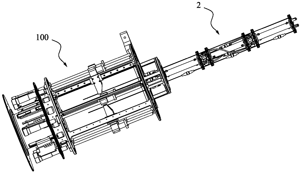
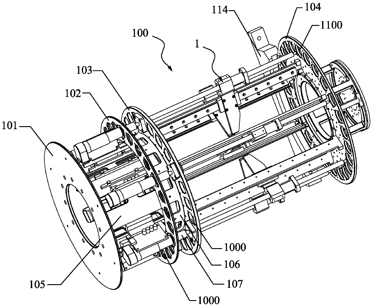
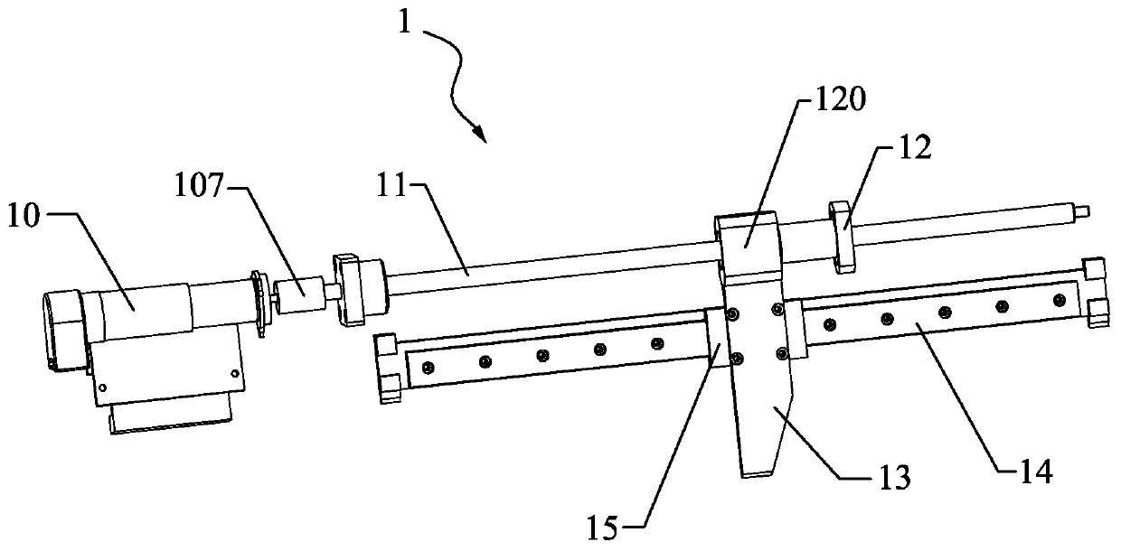
The invention discloses a rope drive flexible robot experimental platform, and belongs to the technical field of robots. The rope drive flexible robot experimental platform comprises flexible arm modules, a drive module, an angle measuring unit and a tensile force measuring unit, wherein the flexible arm modules comprise first arm sections, second arm sections, third arm sections and drive ropes penetrating through the first arm sections, the second arm sections and the third arm sections, the first arm sections are connected with the second arm sections through joints, and the second arm sections are connected with the third arm sections through joints; the drive module comprises a drive part, a screw rod and a screw nut, the drive part can drive the screw rod to rotate, the screw nut isconnected with the screw rod, the screw nut can be driven by rotation of the screw rod to move in the axial direction of the screw rod, and one end of the drive rope is connected with the screw nut; the angle measuring unit is connected with the joints; and the tensile force measuring unit is connected with the drive rope. Actual working conditions of the robots can be simulated through the rope drive flexible robot experimental platform, and motion parameters of the robots can be measured.

Description

technical field [0001] The invention relates to the technical field of robots, in particular to an experimental platform for a rope-driven flexible robot. Background technique [0002] At present, a large number of high-efficiency robots have been widely used in the fields of electrical, chemical, and mechanical manufacturing industries. However, due to the elastic deformation of the rope and the influence of many friction forces, the accuracy of the rope-driven flexible robot has not been high, which affects its use. scope and use. [0003] One of the main factors that makes it difficult to improve the accuracy of rope-driven flexible robots is that there is a certain error between the actual model and the theoretical model. For example, when a rope passes through a circular hole, in order to minimize its movement error, the size of the circular hole should be as small as possible. However, considering the friction factor, the diameter of the circular hole must be larger t...

Claims


Application Information

Patent Timeline
IPC IPC(8): B25J19/00
CPCB25J19/0095
Inventor 徐文福杨太玮刘天亮梁斌
Owner HARBIN INST OF TECH SHENZHEN GRADUATE SCHOOL
Learn More