
Laser radar system

A laser radar and laser beam technology, applied in the field of environmental perception, can solve problems affecting light extraction efficiency, affecting ranging performance, stray light, etc., and achieve the effect of ensuring output efficiency

Active Publication Date: 2019-06-21
HESAI TECH CO LTD
View PDF6 Cites 23 Cited by
  • Summary
  • Abstract
  • Description
  • Claims
  • Application Information

AI Technical Summary

Problems solved by technology

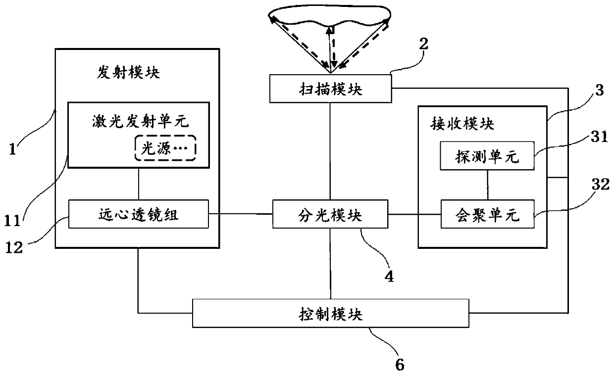
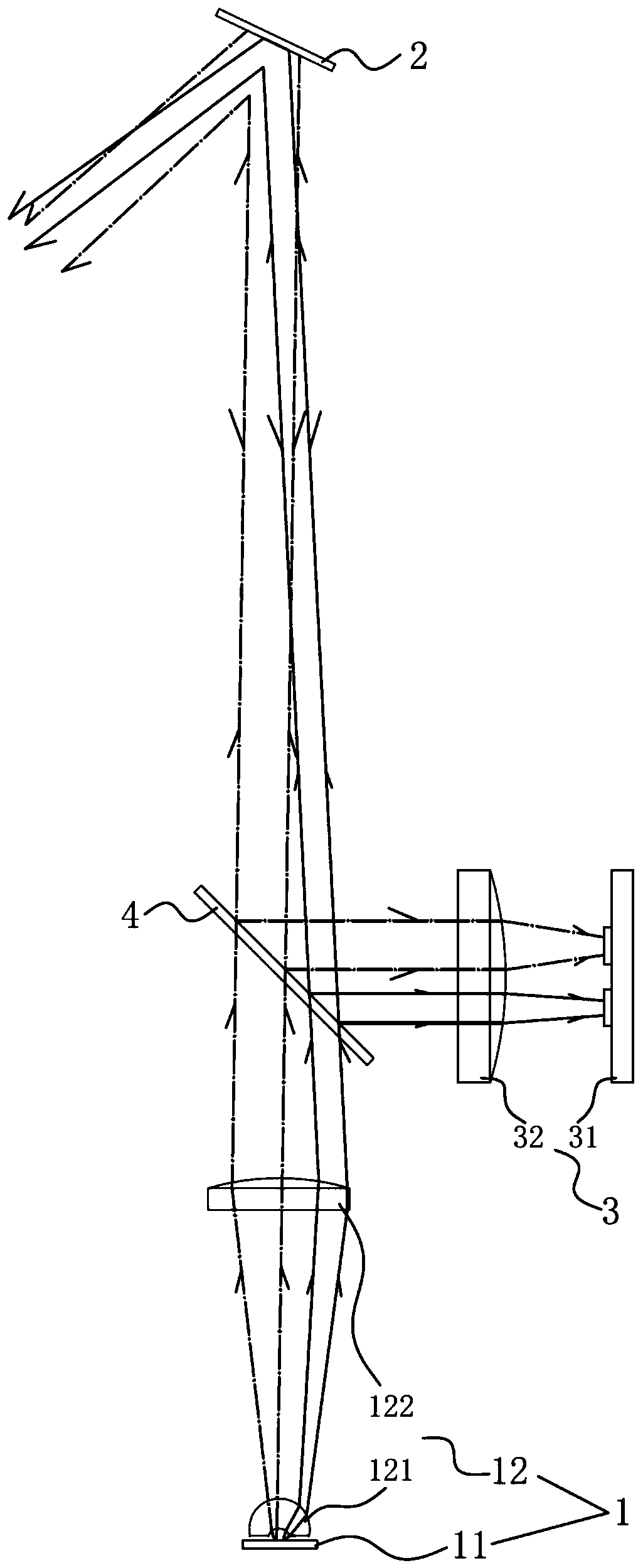
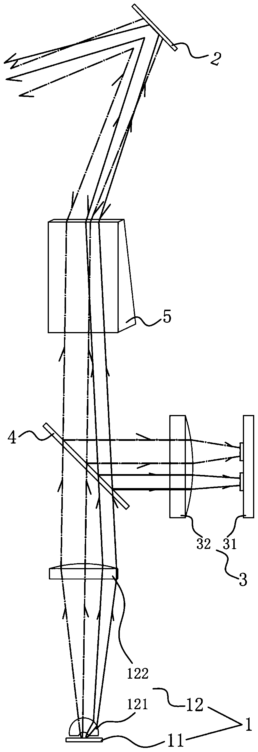
[0005] Since there is a certain distance between the scanning mirror and the collimating lens, different outgoing laser beams will fall on different positions of the scanning mirror. When the size of the scanning mirror is small, some laser beams will fall outside the scanning mirror. On the one hand, it will affect the light extraction efficiency. Affects ranging performance; on the other hand, internal stray light will be formed, resulting in near blind spots

Method used


Image

  • Laser radar system
  • Laser radar system
  • Laser radar system

Examples


Embodiment Construction

[0049] The following will clearly and completely describe the technical solutions in the embodiments of the present invention with reference to the drawings in the embodiments of the present invention. Apparently, the described embodiments are only some of the embodiments of the present invention, not all of them. Based on the embodiments of the present invention, all other embodiments obtained by persons of ordinary skill in the art without creative efforts fall within the protection scope of the present invention.

[0050] Reference herein to "one embodiment" or "an embodiment" refers to a particular feature, structure or characteristic that can be included in at least one implementation of the present invention. In the description of the present invention, it should be understood that the orientation or positional relationship indicated by the terms "upper", "lower", "top", "bottom" etc. is based on the orientation or positional relationship shown in the drawings, and is on...


PUM


Abstract

The invention provides a laser radar system which comprises a transmitting module and a scanning module which are sequentially arranged along a first optical path. The transmitting module comprises alaser transmitting unit and a telecentric lens group; wherein the laser transmitting unit is provided with a plurality of light sources and is used for emitting a plurality of laser beams; the telecentric lens group is used for respectively collimating the laser beams into parallel light beams and enabling the plurality of parallel light beams to be converged along a first light path and transmitted to the scanning module; and the scanning module is used for reflecting the converged parallel light beams to a three-dimensional space and receiving and reflecting echo light beams reflected by a to-be-detected target. The laser radar system can ensure that laser beams emitted at different angles are effectively collimated and emitted, the laser emitting efficiency is ensured to the maximum extent, and the situation that in the working process of the laser radar system, laser beams emitted by a plurality of light sources are partially scattered outside a scanning module to form stray lightcan be avoided.

Description

technical field [0001] The invention relates to the technical field of environment perception, in particular to a laser radar system. Background technique [0002] In autonomous driving technology, the environmental perception system is a basic and crucial part, and it is the guarantee of the safety and intelligence of autonomous vehicles. As an important sensor for perceiving surrounding information, on-board lidar has resolution as one of its important parameters. The higher the resolution of lidar, the richer the information, the more conducive to automatic driving decision-making. [0003] The resolution of lidar using scanning mirrors and other scanning methods is often limited by the scanning frequency of the scanning device. In order to further increase the resolution, it can be realized by correspondingly increasing the number of lasers and detectors. At present, the commonly used technical solution is to use the transmitting collimating lens, the collimating lens...

Claims


Application Information

Patent Timeline
Patent Type & Authority Applications(China)
IPC IPC(8): G01S7/481
CPCG01S7/481
Inventor 吴世祥向少卿
Owner HESAI TECH CO LTD
Learn More