
Backward centrifugal wind wheel

A centrifugal wind wheel and wind wheel technology, which is applied to the components of pumping devices for elastic fluids, non-variable displacement pumps, machines/engines, etc., can solve the problem of low technical performance, low noise quality and noise It can eliminate the phenomenon of gas separation, optimize the flow state, and reduce the aerodynamic noise.

Pending Publication Date: 2019-06-18
ZHONGSHAN EBS TECH CO LTD
View PDF0 Cites 7 Cited by
  • Summary
  • Abstract
  • Description
  • Claims
  • Application Information

AI Technical Summary

Problems solved by technology

[0006] The first purpose of the present invention is to provide a backward centrifugal wind wheel, which solves the technical problems of low technical performance, high noise value and poor noise quality of the binary blades in the prior art due to the binary theory design of the backward centrifugal wind wheel

Method used


Image

  • Backward centrifugal wind wheel
  • Backward centrifugal wind wheel
  • Backward centrifugal wind wheel

Examples


Embodiment 1

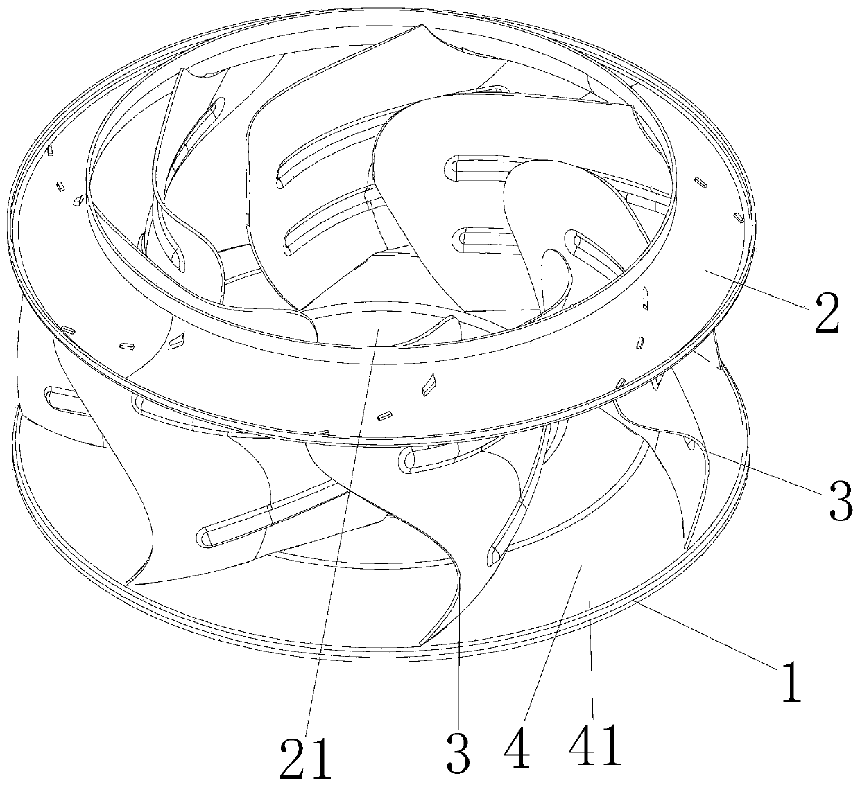
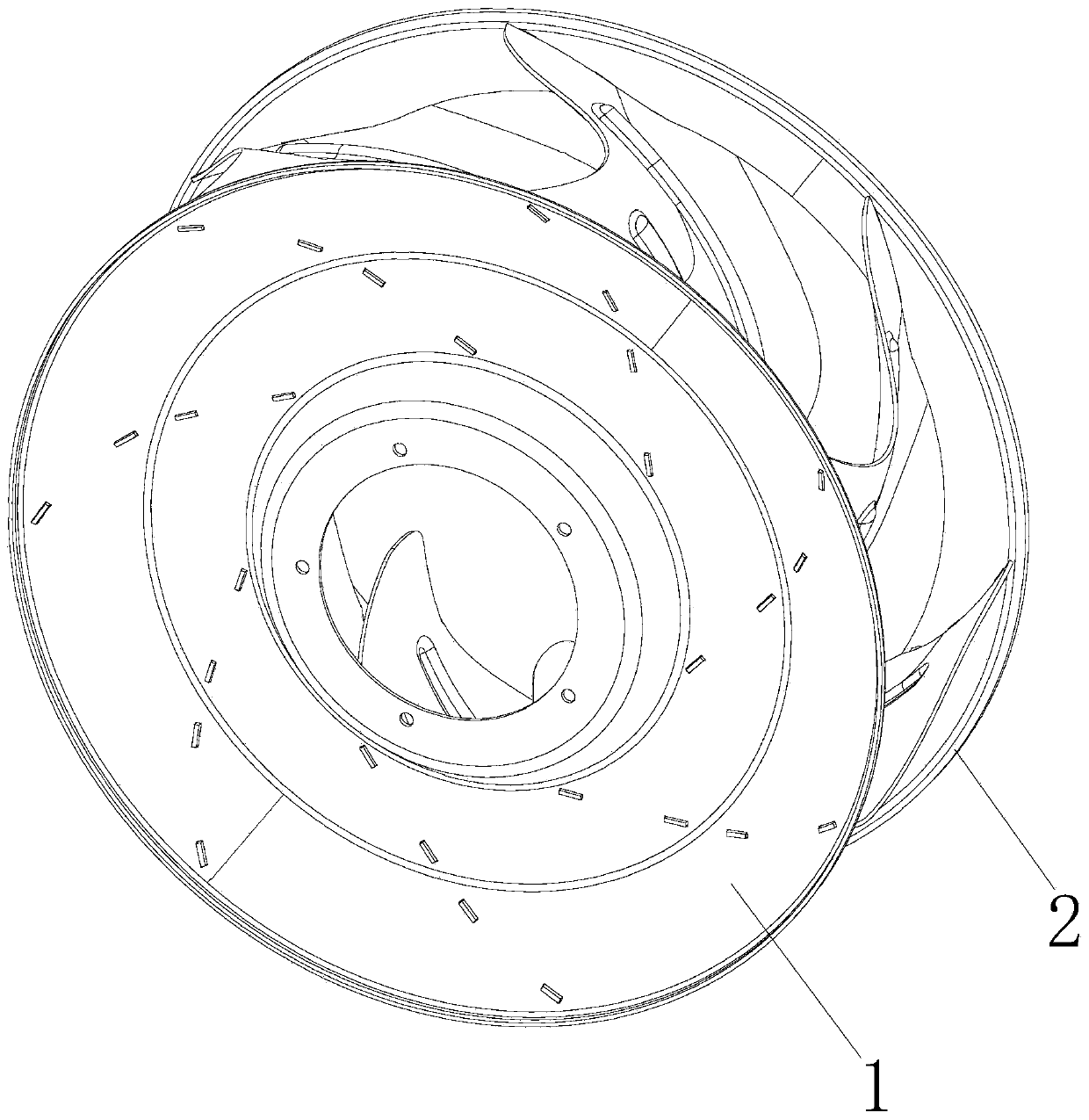
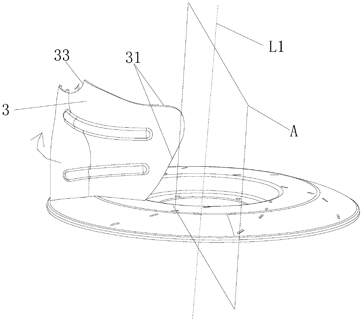
[0042] Such as Figure 1 to Figure 15 As shown, this embodiment provides a backward centrifugal wind wheel, which includes a wheel disc 1 at the bottom, a wheel cover 2 at the top, and several three-dimensional twisted blades 3. The center of the wheel cover 2 is provided with an air inlet 21, and the wheel 1 and the wheel cover 2 are installed with several three-dimensional twisted blades 3, and an air duct 4 is formed between two adjacent three-dimensional twisted blades 3, and an air outlet 41 is formed on the outer edge of the air duct 4. The three-dimensional twisted blades 3 includes a leading edge 31, a trailing edge 32, an upper edge 33, and a lower edge 34, and is characterized in that: a surface passing through the rotor axis L1 is set as a meridian plane A, and when the leading edge 31 rotates along the rotor axis L1, the leading edge 31 When each point on the meridian plane A intersects with a curve L2, the distance between each point on the curve L2 on the meridia...


PUM


Abstract

The invention discloses a backward centrifugal wind wheel. A three-element twisted blade(3) is adopted, a leading edge(31) is rotated along the axis L1 of the wind wheel is intersected with the meridian plane A to form a curve L2, the distance between each point on the curve L2 and the axis L1 of the wind wheel is gradually reduced from the diameter D0 to the axis L1 of the wind wheel, and then the distance is gradually increased from small to small; and the trailing edge (32) and the projection re-plane formed on the cylindrical surface B is unfolded to form a curve L3, the coordinates of thefive curvature inflection points a, b, c, d and e in the curve L3 are coordinates (xa, ya), (xb, yb), (xc,yc), (xd,yd), (xe,ye) wherein the total length of the projection is y, the total width is x.The flow in the whole flow channel is optimized, the pneumatic performance of the impeller is greatly improved, the pneumatic noise of the impeller is reduced, and the noise quality of the impeller isimproved.

Description

Technical field: [0001] The invention relates to a backward centrifugal wind wheel. Background technique: [0002] The impeller in a backward centrifugal fan is generally composed of three parts: a disc, a wheel cover, and a blade. It is used in an installation with a complex environment, and the air intake and air outlet conditions are complex. The impeller blades of backward centrifugal fans are generally designed according to the binary theory. The impeller is generally composed of three parts: the wheel disc, the wheel cover and the blade. The wheel disc, the wheel cover and the blade are stamped respectively. The positioning holes are designed on the wheel disc and the wheel cover, and the positioning block is set on the blade. After passing the positioning block through the positioning hole Flattened and welded, finally joined as an impeller. The above backward centrifugal wind wheel has the following problems and disadvantages: [0003] 1. The backward centrifugal ...

Claims


Application Information

Patent Timeline
Patent Type & Authority Applications(China)
IPC IPC(8): F04D29/30F04D29/28F04D29/66F04D29/00
Inventor 徐海明
Owner ZHONGSHAN EBS TECH CO LTD
Learn More