Ship rotating shaft system phase angle measuring device and method

A technology for measuring devices and phase angles, applied to measuring devices, devices using electric devices, devices using electric/magnetic methods, etc., can solve problems such as harsh environments, cumbersome steps, dust, and oil pollution, and achieve low requirements for installation locations , Easy installation and maintenance, good anti-interference effect

Inactive Publication Date: 2019-06-04
NANJING UNIV OF SCI & TECH
View PDF9 Cites 1 Cited by
  • Summary
  • Abstract
  • Description
  • Claims
  • Application Information

AI Technical Summary

Problems solved by technology

However, when this method is applied to the shafting of a ship, it is usually necessary to install a coupling or perform a shaft breaking operation to install the encoder on the shaft to be measured, and the steps are cumbersome.
In addition, the drive shaft is usually located at the bottom of the cabin, where there is a lot of dust and oil, and the environment is harsh, which will interfere with the measurement of the photoelectric encoder
Coupled with the vibration of the transmission shaft itself during operation, it is difficult to guarantee the measurement accuracy
Moreover, limited by the technical level, the division value of the photoelectric encoder is usually low, making it difficult to achieve a high standard in the measurement accuracy and measurement frequency of the phase angle of the rotating shaft.

Method used


Image

  • Ship rotating shaft system phase angle measuring device and method
  • Ship rotating shaft system phase angle measuring device and method
  • Ship rotating shaft system phase angle measuring device and method

Examples


Embodiment Construction

[0026] The solutions of the present invention will be further described below in conjunction with the accompanying drawings and specific embodiments.

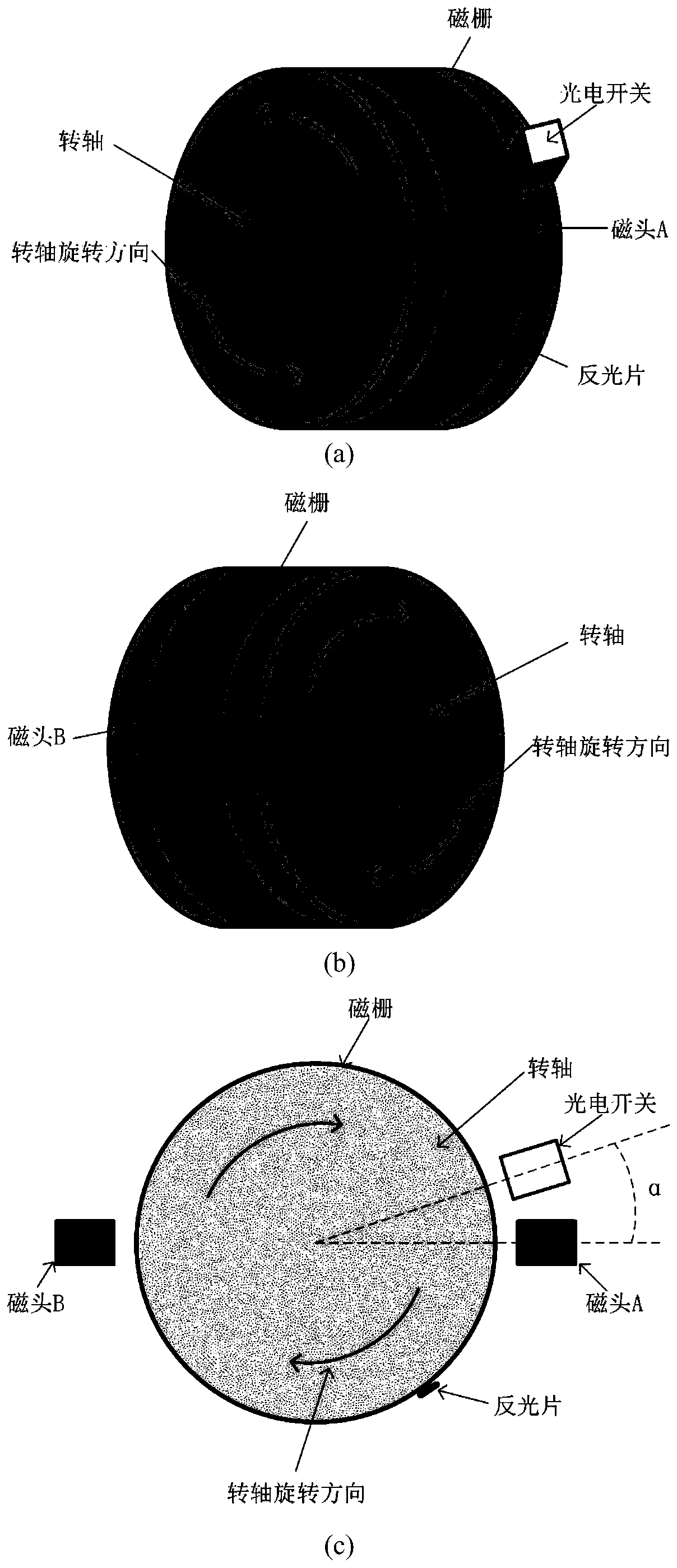
[0027] Such as figure 1 As shown, the ship rotating shafting phase angle measuring device of the present invention includes a magnetic grid strip, a magnetic reading head A, a magnetic reading head B, a photoelectric switch, a reflective sheet, a direction discrimination decoupling circuit, a signal acquisition unit, and a phase angle calculation unit, The magnetic grid strips surround the surface of the ship's rotating shaft to be tested, and the ring formed is coaxial with the rotating shaft to be measured; the magnetic read head A and magnetic read head B are arranged above the magnetic grid bar, symmetrical about the rotating shaft, and the two magnetic read heads The effective sensing surface of the head faces the magnetic grid bar, tangent to the ring of the magnetic grid bar, and the direction of its long side should be ...


PUM


Abstract

The invention discloses a ship rotating shaft phase angle measuring device and method. The device comprises a magnetic grating strip, a magnetic read head A, a magnetic read head B, a photoelectric switch, a reflective sheet, a discriminating decoupling circuit, a signal collecting unit and a phase angle calculating unit. The magnetic grating strip surrounds the surface of a to-be-measured rotating shaft of a ship to form a ring coaxial with the rotating shaft. The magnetic read head A and the magnetic read head B are symmetrically arranged above the magnetic grating strip, and the effective sense surfaces thereof face the magnetic grating strip and are tangent to the ring of the magnetic grating strip. The direction of the long side should be the same as the rotation direction of the magnetic grating strip. The magnetic grating pulse signals output by A and B have a phase difference. The reflective sheet is arranged on a ring face adjacent to the magnetic grating strip. The photoelectric switch is arranged above the ring face in which the reflective sheet is located. After the discriminating decoupling circuit discriminates and decouples two pulse signals. The collecting unit carries out unified counting to calculate the current phase angle of the rotating shaft. The device provided by the invention has the advantages of convenient installation, good reliability, high phase angle measurement accuracy, fast frequency and good low speed performance.

Description

technical field [0001] The invention relates to the measurement of the phase angle of a ship's rotating shaft system, in particular to a device and method for measuring the phase angle of a ship's rotating shaft system. Background technique [0002] Shafting is an important part of the entire ship power system and the core of power transmission between the main engine and the propeller. Its stability during operation directly affects the navigation performance and safety of the ship. Due to the influence of the excitation generated by the main engine, the bending deformation caused by the self-weight of the shaft system, the resistance torque and thrust generated by the propeller, etc., the shaft system will inevitably vibrate during operation. When the vibration of the shaft system reaches a certain level, it will cause the failure of the shaft system and the main engine, reduce the power transmission efficiency, and even cause the vibration of the main engine body and the ...

Claims


Application Information

Patent Timeline
Patent Type & Authority Applications(China)
IPC IPC(8): G01B7/30G01P3/44
Inventor 冯延晖黄光远邱颖宁任铭徐晨
Owner NANJING UNIV OF SCI & TECH
Why Eureka
Try Eureka