
Electronic control system and variable fuel injection pressure control method for internal combustion engine

一种电子控制系统、喷油压力的技术,应用在电气控制、发动机控制、燃料喷射控制等方向,能够解决无法实现喷油压力实时变化调整等问题,达到避免湿壁效应、减少PN排放的效果

Active Publication Date: 2022-06-24
UNITED AUTOMOTIVE ELECTRONICS SYST
View PDF17 Cites 0 Cited by
  • Summary
  • Abstract
  • Description
  • Claims
  • Application Information

AI Technical Summary

Problems solved by technology

[0006] One of the purposes of the present invention is to solve the technical problem that a single fuel supply and injection mode cannot realize real-time adjustment of fuel injection pressure with working conditions

Method used


Image

  • Electronic control system and variable fuel injection pressure control method for internal combustion engine
  • Electronic control system and variable fuel injection pressure control method for internal combustion engine
  • Electronic control system and variable fuel injection pressure control method for internal combustion engine

Examples


Embodiment 1

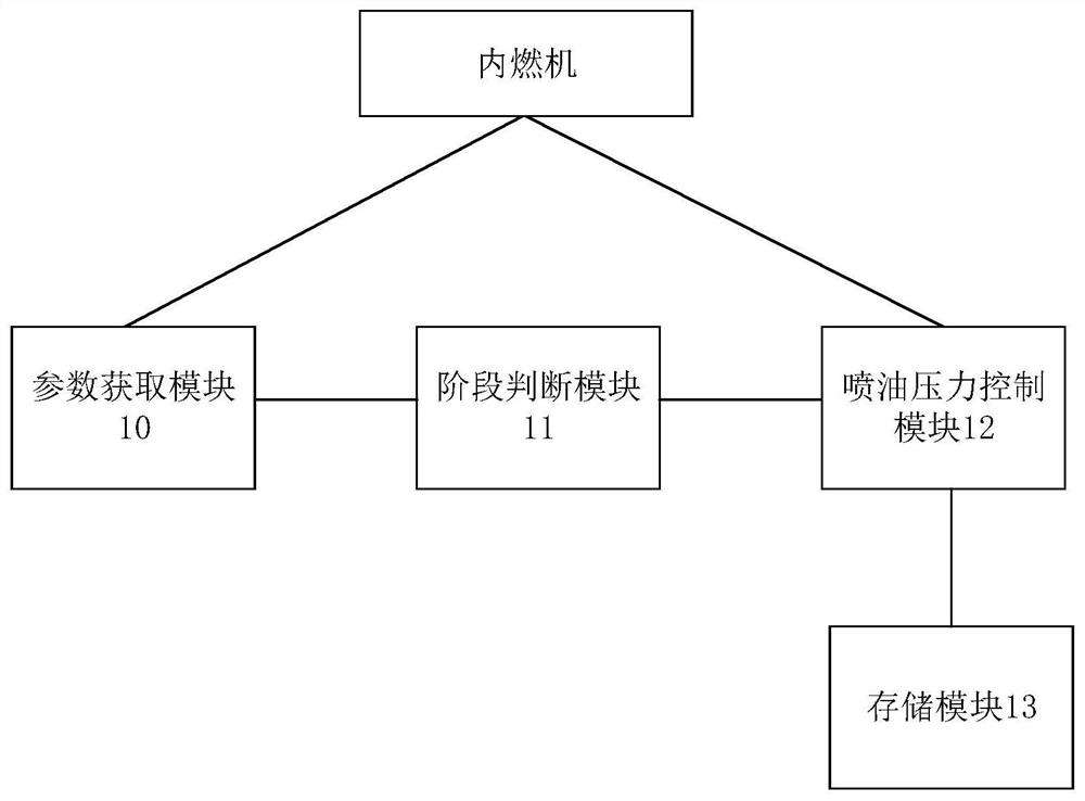
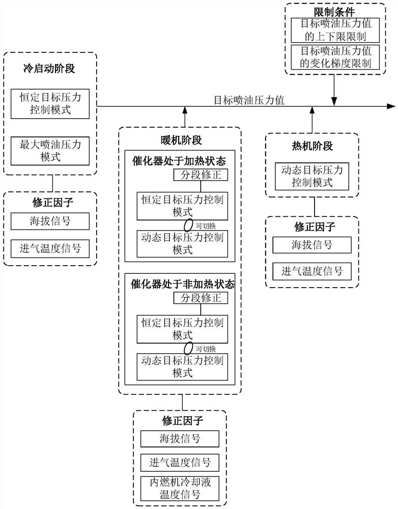
[0060] Please refer to figure 1 , which is a schematic structural diagram of the electronic control system in this embodiment. like figure 1 As shown, the electronic control system includes: a storage module 13, a parameter acquisition module 10, a phase judgment module 11 and a fuel injection pressure control module 12, and the storage module 13 is used to store the target fuel injection pressure list of each working stage of the internal combustion engine, The target fuel injection pressure list is a table about the corresponding relationship between working stage influencing parameters and target fuel injection pressure values, and the working stage includes a cold start stage, a warm-up stage and a warm-up stage; the parameter acquisition module 10 is used to obtain The working stage judgment parameter and the current working stage influencing parameter of the current internal combustion engine; the stage judgment module 11 is used to judge the current working stage of th...

Embodiment 2

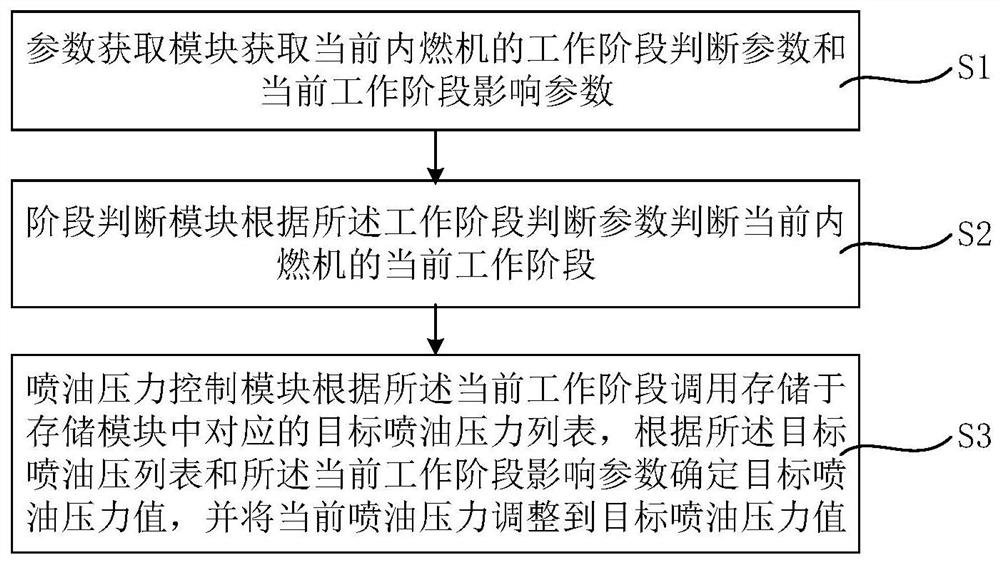
[0068] Please refer to figure 2 , which is a flow chart of the method for controlling the variable fuel injection pressure of the internal combustion engine in this embodiment. like figure 2 As shown, the variable fuel injection pressure control method of the internal combustion engine uses the electronic control system as described above. The internal combustion engine burns the fuel inside the machine and converts the heat energy released by it directly into a thermal internal combustion engine for power. The internal combustion engine The variable fuel injection pressure control method mainly includes the following steps:

[0069] Firstly, step S1 is executed: the parameter acquisition module acquires the working stage judgment parameters of the current internal combustion engine and the influencing parameters of the current working stage;

[0070] Next, step S2 is executed: the stage judging module judges the current working stage of the current internal combustion eng...


PUM


Abstract

The present invention provides an electronic control system and a method for controlling variable fuel injection pressure of an internal combustion engine. The method for controlling variable fuel injection pressure of an internal combustion engine includes: a parameter acquisition module acquiring the current working stage judgment parameters of the internal combustion engine and the current working stage influencing parameters; the stage judging module judges the current working stage of the current internal combustion engine according to the working stage judging parameter; the fuel injection pressure control module calls the corresponding target fuel injection pressure list stored in the storage module according to the current working stage, Determine a target fuel injection pressure value according to the target fuel injection pressure list and the current working stage influencing parameters, and adjust the current fuel injection pressure to the target fuel injection pressure value. The control method can adjust the fuel injection pressure based on the real-time working conditions of the internal combustion engine, so as to ensure the optimal discharge of various gaseous substances, and the emissions comply with the relevant emission regulations.

Description

technical field [0001] The invention relates to the field of automobile engine control, in particular to an electronic control system and a method for controlling variable fuel injection pressure of an internal combustion engine. Background technique [0002] The system fuel injection pressure of traditional Port Fuel Injection gasoline engine PFI (PortFuel Injection) is limited by the pressure regulating valve and all working conditions are kept constant. The fuel pump will continue to deliver fuel to the fuel rail to maintain the basic injection pressure of the injector. This single fuel supply injection mode cannot realize real-time changes in fuel injection pressure with operating conditions. [0003] The National V emission regulations only limit gaseous pollutants for PFI engines, and the New European Driving Cycle (NEDC) is relatively stable. The traditional constant pressure injection mode will not affect the PFI engine to meet the requirements of the National V emis...

Claims


Application Information

Patent Timeline
Patent Type & Authority Patents(China)
IPC IPC(8): F02D41/30F02D41/14F02D41/06
Inventor 赵翔张振宇曹银波
Owner UNITED AUTOMOTIVE ELECTRONICS SYST
Learn More