
Antenna installation support for emergency mobile base station and installation method of antenna installation support

A technology for installing brackets and mobile base stations, which is applied to antenna supports/installation devices, etc., can solve the problems of inconvenient disassembly, high labor cost, time-consuming and laborious adjustment, etc., and achieves the effect of convenient disassembly, low labor cost, and elimination of potential safety hazards.

Active Publication Date: 2019-05-14
江西硕天宇无线技术有限公司
View PDF9 Cites 6 Cited by
  • Summary
  • Abstract
  • Description
  • Claims
  • Application Information

AI Technical Summary

Problems solved by technology

[0003] In order to make up for the deficiencies in the prior art, the present invention provides an antenna mounting bracket for emergency mobile base stations and its installation method, which can solve the inconvenience of disassembly, time-consuming and laborious adjustment, high labor costs and potential safety hazards during the installation process of antennas for emergency mobile base stations and other problems, it can realize the function of automatically adjusting the antenna angle of the emergency mobile base station, which has the advantages of convenient disassembly, convenient adjustment, low labor cost and high degree of safety.

Method used


Image

  • Antenna installation support for emergency mobile base station and installation method of antenna installation support
  • Antenna installation support for emergency mobile base station and installation method of antenna installation support
  • Antenna installation support for emergency mobile base station and installation method of antenna installation support

Examples


Embodiment Construction

[0025] In order to make the technical means, creative features, goals and effects achieved by the present invention easy to understand, the present invention will be further described below in conjunction with specific illustrations.

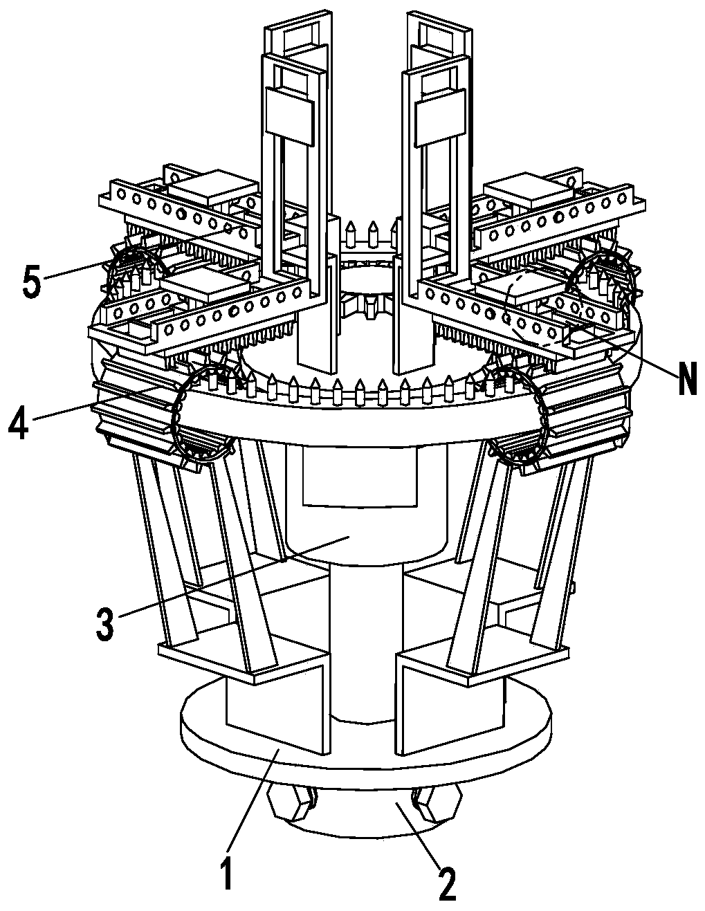
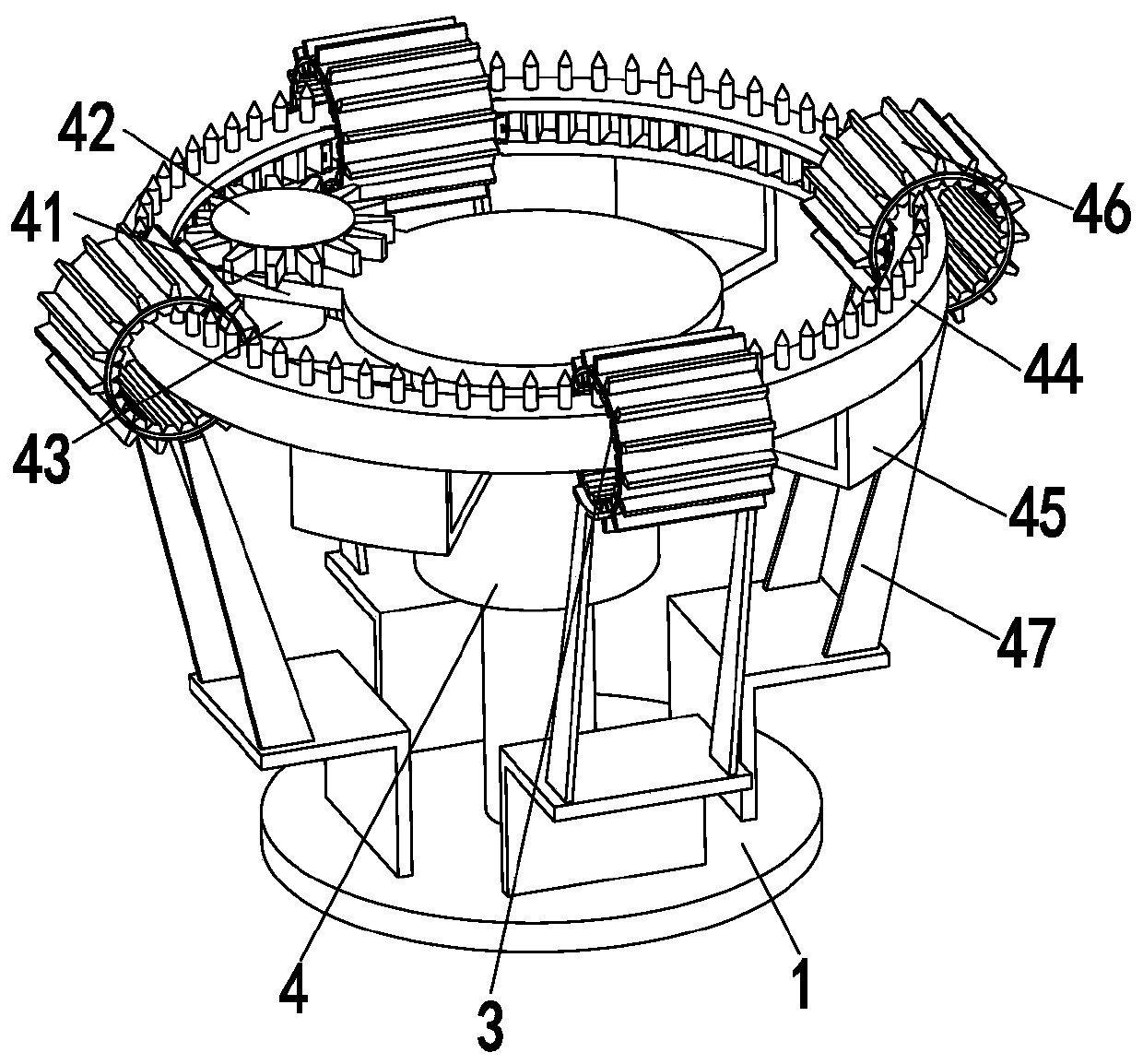
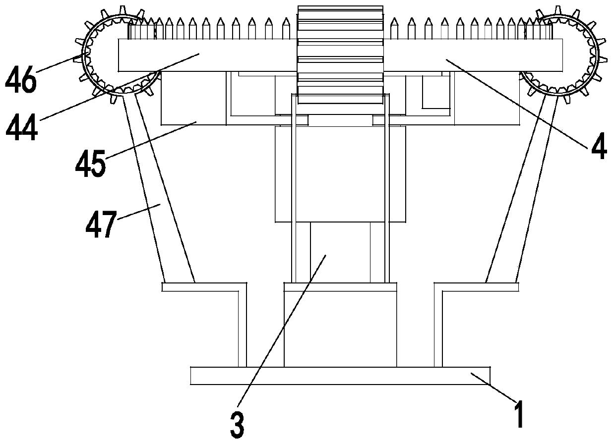
[0026] Such as Figure 1 to Figure 5 As shown, an antenna mounting bracket for an emergency mobile base station includes a base plate 1, a connecting cylinder 2, a support column 3, an adjustment mechanism 4, and a mounting mechanism 5. There is a circular hole in the middle of the base plate 1, and a connecting cylinder is installed at the lower end of the circular hole. 2. A support column 3 is installed on the upper end of the round hole, and a rotation groove is opened on the side wall of the support column 3. An adjustment mechanism 4 is installed on the upper end of the support column 3, and an installation mechanism 5 is installed on the upper end of the adjustment mechanism 4. The installation mechanism 5 is installed on the support colum...


PUM


Abstract

The invention relates to an antenna installation support for an emergency mobile base station. The antenna installation support comprises a base plate, a connecting cylinder, a supporting column, an adjustment mechanism and an installation mechanism, wherein a round hole is formed in the middle of the base plate, the connecting cylinder is installed at the lower end of the round hole, the supporting column is installed at the upper end of the round hole, a rotary slot is formed in the side wall of the supporting column, the adjustment mechanism is installed at the upper end of the supporting column, the installation mechanism is arranged at the upper end of the adjustment mechanism, and the installation mechanism is installed on the supporting column. The invention furthermore provides aninstallation method of the antenna installation support for the emergency mobile base station. The method comprises the steps of first, antenna installation; second, fixation to a base station liftingrod; third, primary adjustment of an angle; fourth, fine adjustment of the angle; and fifth, angle fixation. Through the antenna installation support and the installation method, the problems that inthe installation process of an antenna for the emergency mobile base station, dismantling is not convenient, adjustment wastes time and labor, manual cost is high, and a potential safety hazard exitscan be solved, and the function of automatically adjusting the angle of the antenna for the emergency mobile base station can be achieved.

Description

technical field [0001] The invention relates to the field of communication equipment, in particular to an antenna installation bracket for an emergency mobile base station and an installation method thereof. Background technique [0002] In the mobile communication business, only the user's terminal moves, and the operator's base station, optical cable, switch and other equipment cannot be moved. Therefore, when natural disasters or safety production accidents occur. These immobile facilities are easily destroyed. Once a major accident occurs, there will be a situation where the mobile phone has no signal, and an emergency mobile base station needs to be used at this time. Before the emergency mobile base station is used, it is necessary to install the antenna and adjust the position of the antenna in order to receive the signal. At present, most of the antenna positions are adjusted manually, which requires the staff to adjust the angle of the antenna one by one at a high...

Claims


Application Information

Patent Timeline
Patent Type & Authority Applications(China)
IPC IPC(8): H01Q1/12H01Q1/24
Inventor 翟森
Owner 江西硕天宇无线技术有限公司
Learn More