
Method and system for anisotropic velocity modeling

An anisotropic and velocity modeling technology, applied in the field of petroleum exploration, can solve problems such as long iteration cycle, low iteration efficiency, anisotropic velocity model error, etc.

Active Publication Date: 2019-05-07
BC P INC CHINA NAT PETROLEUM CORP +1
View PDF12 Cites 3 Cited by
  • Summary
  • Abstract
  • Description
  • Claims
  • Application Information

AI Technical Summary

Problems solved by technology

[0003] At present, the TTI (tilted transversely isotropic, tilted transverse isotropic) anisotropic velocity model commonly used in industrial production has a long iteration cycle and low iteration efficiency in the modeling process, and the established anisotropic velocity model has a large discrepancy with the actual data. error

Method used


Image

  • Method and system for anisotropic velocity modeling
  • Method and system for anisotropic velocity modeling
  • Method and system for anisotropic velocity modeling

Examples


Embodiment Construction

[0094] The following will clearly and completely describe the technical solutions in the embodiments of the present invention with reference to the accompanying drawings in the embodiments of the present invention. Obviously, the described embodiments are only some, not all, embodiments of the present invention. Based on the embodiments of the present invention, all other embodiments obtained by persons of ordinary skill in the art without making creative efforts belong to the protection scope of the present invention.

[0095] In view of the fact that the modeling process of the existing anisotropic velocity model has a long iteration period and low iteration efficiency, and there is a large error between the established anisotropic velocity model and the actual data, the embodiment of the present invention provides an anisotropic velocity model Modeling method to shorten the iteration cycle, improve the iteration efficiency, reduce the error with the actual data, and improve ...


PUM


Abstract

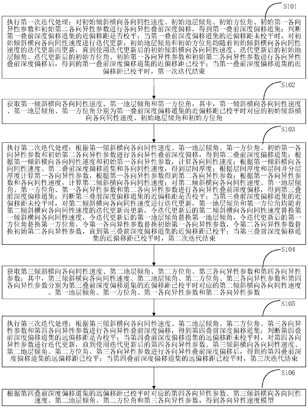
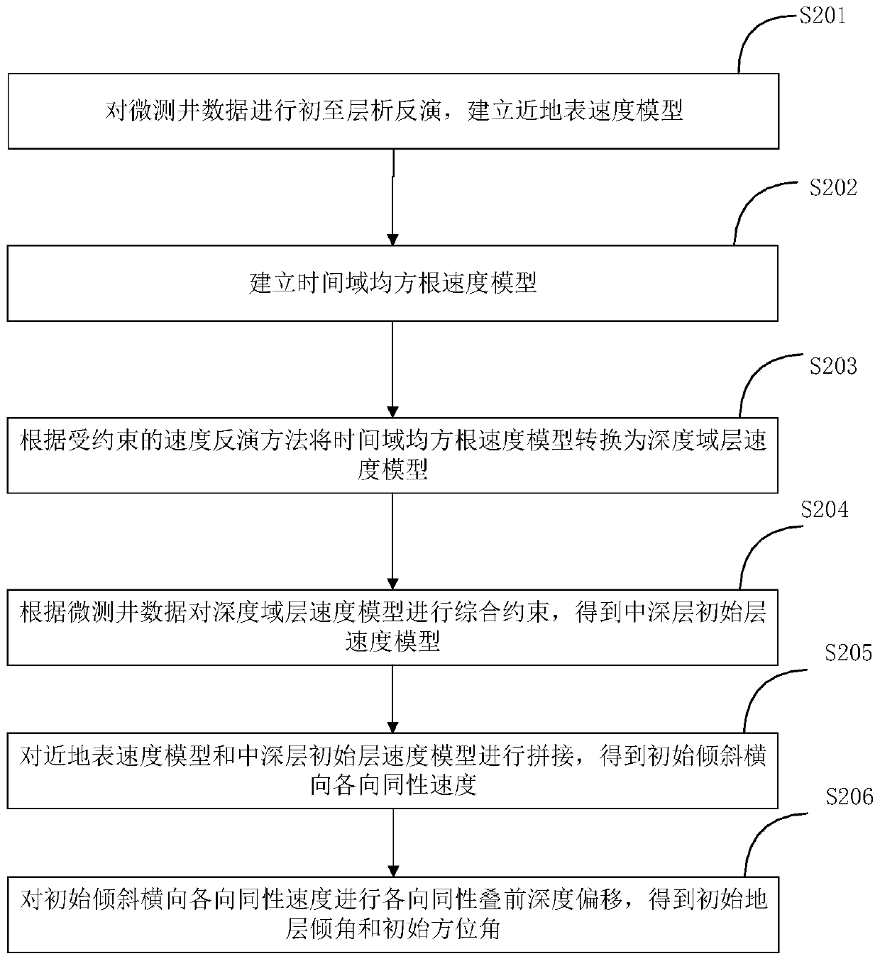
The invention provides a method and a system for anisotropic velocity modeling. The method for the anisotropic velocity modeling comprises performing a first iteration process to obtain an initial inclined lateral isotropic velocity, an initial formation dip angle, and an initial azimuth angle corresponding to the time that a near-offset of a first pre-stack depth migration gather has been leveled; performing a second iteration process to obtain a second inclined lateral isotropic velocity, a first formation dip angle, a first azimuth angle, a first anisotropic parameter, and a second anisotropic parameter corresponding to the time that the near-offset of a third pre-stack depth migration gather has been leveled; performing a third iteration process to obtain a fourth anisotropic parametercorresponding to the time that the near-offset of a fourth pre-stack depth migration gather has been leveled; and obtaining an anisotropic velocity model based on the fourth anisotropic parameter, athird inclined lateral isotropic velocity, a second formation dip angle, a second azimuth angle, and a third anisotropic parameter. According to the method and the system for the anisotropic velocitymodeling, the iteration cycle can be shortened; the accuracy of the offset imaging can be improved; and the error between the detected data and the real data can be reduced.

Description

technical field [0001] The invention relates to the field of petroleum exploration, in particular to an anisotropic velocity modeling method and system. Background technique [0002] Prestack depth migration imaging technology is the key technology for accurate imaging of complex structures, which has been generally recognized. Since the assumption of anisotropy is closer to the actual subsurface medium than the assumption of isotropy, the pre-stack depth migration imaging technology based on the anisotropy assumption is more common in industrial production applications. The key to determining the quality of prestack depth migration imaging is the accuracy of the anisotropic velocity model, and the modeling of the anisotropic velocity model is the core of the prestack depth migration imaging processing of complex high and steep structures in the piedmont. [0003] At present, the TTI (tilted transversely isotropic, tilted transverse isotropic) anisotropic velocity model com...

Claims


Application Information

Patent Timeline
IPC IPC(8): G01V1/40
Inventor 罗文山罗晓霞方勇袁燎高现俊张胜
Owner BC P INC CHINA NAT PETROLEUM CORP
Learn More