Eureka AIR delivers breakthrough ideas for toughest innovation challenges, trusted by R&D personnel around the world.

A single shoe pin brake

A technology of brakes and brake shoes, applied in the direction of brake parts, mechanically driven drum brakes, brake actuators, etc., can solve the problem of reducing the restoring force of a single brake spring, inconvenient for brake disassembly and maintenance, and reducing the return of brake shoes. effect and other issues to achieve the effect of improving service life, avoiding moisture contact, and increasing recovery effect.

Active Publication Date: 2021-05-28
TAIZHOU SHENZHOU TRANSMISSION TECH
View PDF0 Cites 0 Cited by
  • Summary
  • Abstract
  • Description
  • Claims
  • Application Information

AI Technical Summary

Problems solved by technology

[0004] 1. During the use of existing cars, the wheels are in the air for a long time, and the car will pass through some low-lying areas during driving, so that some water will seep into the inside of the brake. If the brake shoe is in contact with water for a long time It is easy to rust, thereby reducing the service life of the brake. Most of the existing brakes adopt a fully-wrapped shoe pin structure. This structure is not convenient for users to disassemble and maintain the brake.
[0005] 2. Most of the existing brakes only use a single brake spring to complete the recovery of the brake after braking. After the brake is used for a long time, the recovery force of a single brake spring may decrease, thereby reducing the recovery effect of the brake shoe

Method used

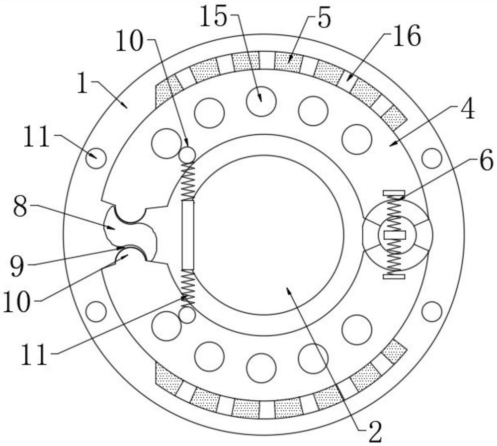
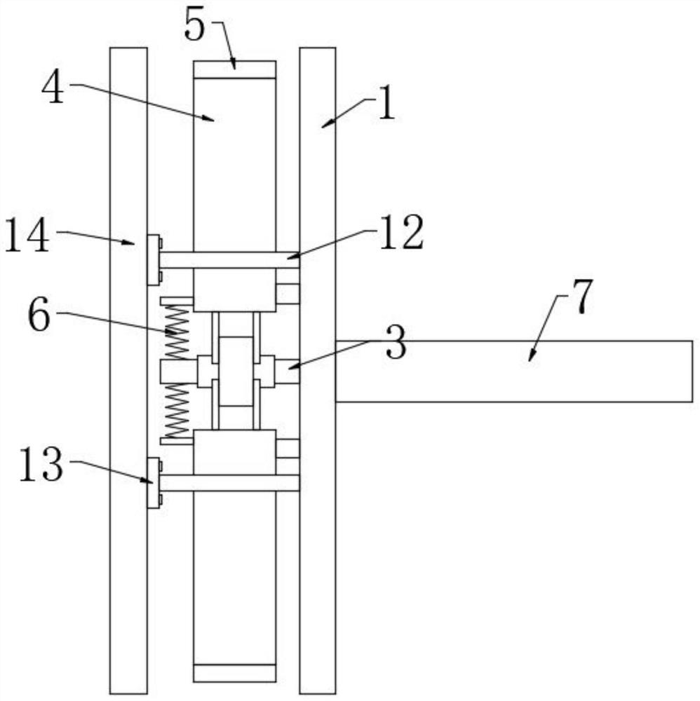

Image

  • A single shoe pin brake
  • A single shoe pin brake
  • A single shoe pin brake

Examples


Embodiment Construction

[0022] The following will clearly and completely describe the technical solutions in the embodiments of the present invention with reference to the accompanying drawings in the embodiments of the present invention. Obviously, the described embodiments are only some, not all, embodiments of the present invention. Based on the embodiments of the present invention, all other embodiments obtained by persons of ordinary skill in the art without making creative efforts belong to the protection scope of the present invention.

[0023] see Figure 1-3 , the present invention provides a technical solution: a single shoe pin brake, including a mounting plate 1, a mounting hole 2 is opened inside the mounting plate 1, and a second mounting hole 2 is fixed on one side of the mounting plate 1 A connecting rod 3, one side of the mounting plate 1 is provided with a brake shoe 4 on both sides of the end of the first connecting rod 3 away from the mounting plate 1 through a rotating shaft, and...


PUM


Abstract

The invention discloses a single-shoe pin brake, which comprises a mounting plate. A mounting hole is opened inside the mounting plate. A first connecting rod is fixedly arranged at one end of the mounting hole on one side of the mounting plate. On both sides of the end of the first connecting rod far away from the mounting plate, brake shoes are movable through the rotating shaft, and high-performance friction plates are fixed on the side of the brake shoe away from the mounting hole, and the brake shoes are far away from the mounting plate. One side of the first connecting rod is installed with the first brake spring through the installation groove on both sides, and the end of the first brake spring far away from the brake shoe is fixedly connected with the end of the first connecting rod far away from the mounting plate. A brake shaft is fixedly arranged at one end of the mounting plate away from the brake shoe. In the present invention, the shoe pin of the brake shoe is a split type and has a roller structure. If the brake breaks down, it can be easily disassembled by the user and convenient for maintenance.

Description

technical field [0001] The invention relates to the technical field of brakes, in particular to a single-shoe pin brake. Background technique [0002] A brake is a device that has the functions of decelerating, stopping or keeping a moving part (or moving machinery) in a stopped state. It is a mechanical part that stops or slows down the moving parts in the machine. Commonly known as brakes, brakes. . [0003] Existing brakes have the following deficiencies: [0004] 1. During the use of existing cars, the wheels are in the air for a long time, and the car will pass through some low-lying areas during driving, so that some water will seep into the inside of the brake. If the brake shoe is in contact with water for a long time It is easy to rust, thereby reducing the service life of the brake. Most of the existing brakes adopt a fully-wrapped shoe pin structure, which is inconvenient for users to disassemble and maintain the brake. [0005] 2. Most existing brakes only u...

Claims


Application Information

Patent Timeline
Patent Type & Authority Patents(China)
IPC IPC(8): F16D51/22F16D65/04F16D65/14F16D121/14
Inventor 殷劲松丁志朋孙成钢方维陈晖
Owner TAIZHOU SHENZHOU TRANSMISSION TECH
Why Eureka
Eureka Blog
Learn More