
Metal plate material placement rack with anti-pinching-hand structure

A metal sheet, placing rack technology, used in storage devices, transportation and packaging, conveyors, etc., can solve the problems of easy pinching of fingers, inability to adjust the height of the sheet, low safety, etc., to improve the stability and movement stability. improve the flexibility and convenience of use, the effect of flexibility of use

Active Publication Date: 2019-04-16
温州市简弈科技有限公司
View PDF8 Cites 1 Cited by
  • Summary
  • Abstract
  • Description
  • Claims
  • Application Information

AI Technical Summary

Problems solved by technology

[0004] Generally, when storing metal plates, in order to facilitate classification and access, horizontal plate shelves or vertical plate shelves are usually used, but the stability of vertical plate shelves is poor, and it is easy to cause plates to dump, while horizontal plate shelves are relatively stable. In addition, there is generally a roller structure, which is convenient for pulling out the boards. However, the storage height of the horizontal board shelves is fixed, and the height of the board storage cannot be adjusted. It is necessary to use a crane or a forklift to assist in accessing the storage at too high and too low positions. Plates have low flexibility in use, and the storage positions are all flat structures, which are easy to pinch fingers and have low safety

Method used

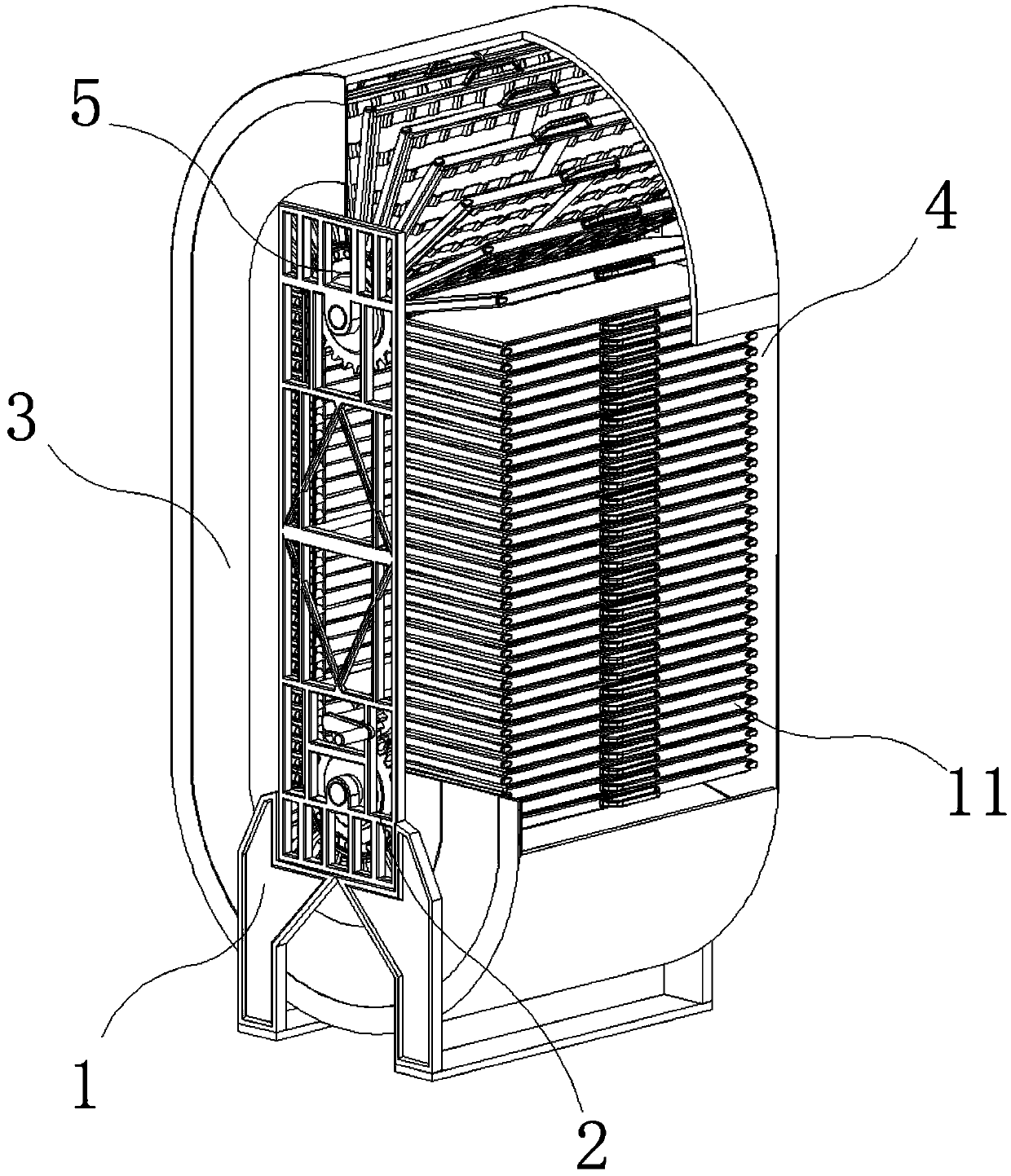
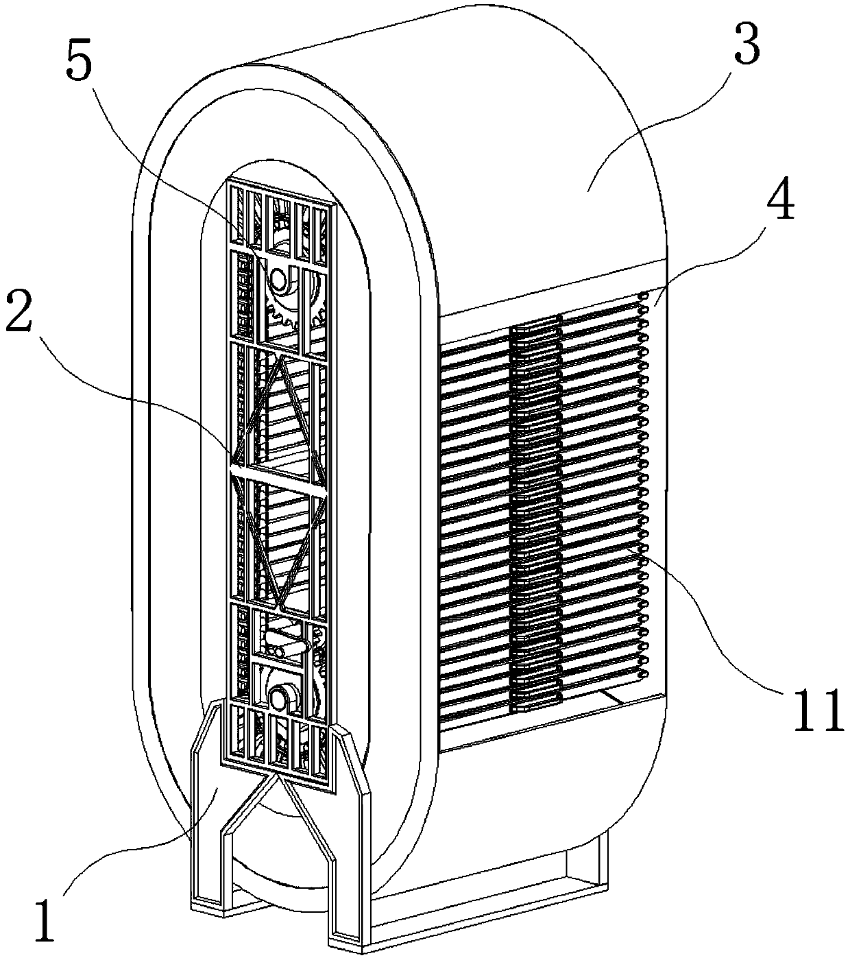
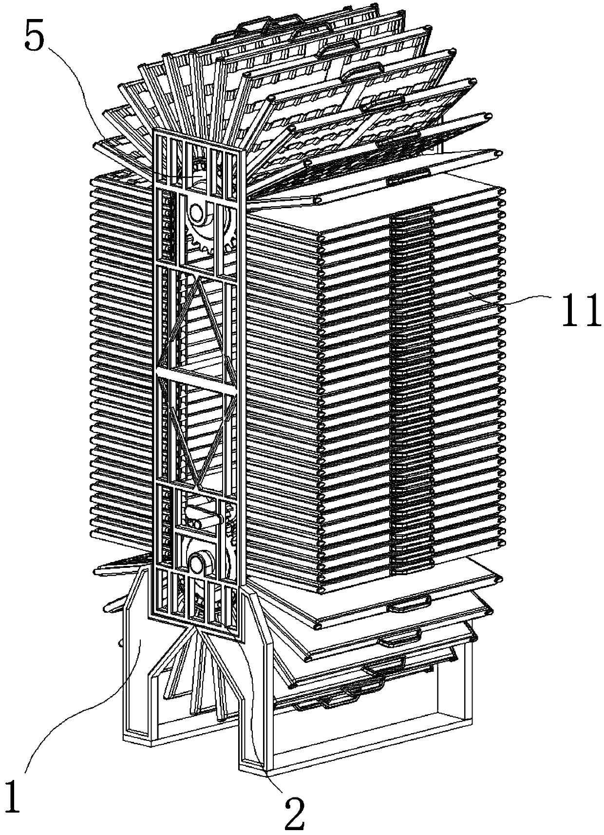

Image

  • Metal plate material placement rack with anti-pinching-hand structure
  • Metal plate material placement rack with anti-pinching-hand structure
  • Metal plate material placement rack with anti-pinching-hand structure

Examples


Embodiment Construction

[0036] The following will clearly and completely describe the technical solutions in the embodiments of the present invention with reference to the accompanying drawings in the embodiments of the present invention. Obviously, the described embodiments are only some, not all, embodiments of the present invention.

[0037] In the description of the present invention, unless otherwise stated, the meaning of "plurality" is two or more; the terms "upper", "lower", "left", "right", "inner", "outer" , "front end", "rear end", "head", "tail", etc. indicate the orientation or positional relationship based on the orientation or positional relationship shown in the drawings, and are only for the convenience of describing the present invention and simplifying the description, rather than Nothing indicating or implying that a referenced device or element must have a particular orientation, be constructed, and operate in a particular orientation should therefore not be construed as limiting ...


PUM


Abstract

The invention discloses a metal plate material placement rack with an anti-pinching-hand structure and relates to the technical field of metal plate material storage. The metal plate material placement rack specifically comprises a base and a translation placement mechanism, wherein the upper portion of the base is fixedly provided with a support, the side face of the support is provided with a protective shell, the front face of the protective shell is provided with a material fetching mouth, the middle of the support is provided with a vertical circulation mechanism, the inner side of the vertical circulation mechanism is provided with a speed reducing gear, the upper portion of the speed reducing gear is connected with a transmission gear, the inner side of the transmission gear is connected with a motor, the outer side of the transmission gear is connected with an operation rocking handle, and the outer side of the vertical circulation mechanism is provided with a balance guide mechanism. According to the metal plate material placement rack with the anti-pinching-hand structure, by means of a moving adjusting mechanism composed of the vertical circulation mechanism, flexibilityadjustment can be performed on the position and height of stored plate materials, the plate materials are conveniently adjusted to the proper height to be fetched and used, and improvement of the useflexibility and convenience of the metal plate material placement rack with the anti-pinching-hand structure is facilitated.

Description

technical field [0001] The invention relates to the technical field of sheet metal storage, in particular to a sheet metal storage rack with an anti-pinch structure. Background technique [0002] Metal sheets are generally forged, rolled or cast metal sheets, and most of them are made into standard-sized flat rectangular building material sheets, which are mostly used in manufacturing and construction industries. [0003] Metal sheet products are flat in shape, large in width-to-thickness ratio, and have a large surface area per unit volume, so they have strong containment and coverage capabilities. They are widely used in chemical industry, containers, construction, metal products, metal structures, etc., and can be cut, bent, and stamped arbitrarily. , welded, and made into various product components. It is flexible and convenient to use. It occupies an extremely important position in the departments of automobile, aviation, shipbuilding and tractor manufacturing. It can b...

Claims


Application Information

Patent Timeline
Patent Type & Authority Applications(China)
IPC IPC(8): B65G1/06
CPCB65G1/127B65G2201/022
Inventor 董伟铭
Owner 温州市简弈科技有限公司
Learn More