
Tidal power station multi-working-condition turbine based on contra-rotating dual-rotor permanent magnet motor

A permanent magnet motor, tidal power station technology, applied in electromechanical devices, electrical components, mechanical equipment and other directions, can solve the problems of inability to improve efficiency, unsatisfactory operating conditions, etc., to achieve high utilization of rotor core, conducive to stable flow, The effect of reducing the moment of inertia

Inactive Publication Date: 2019-04-09
JIANGSU UNIV
View PDF8 Cites 2 Cited by
  • Summary
  • Abstract
  • Description
  • Claims
  • Application Information

AI Technical Summary

Problems solved by technology

[0006] Aiming at the problems that the common efficiency of the single-impeller tubular water turbines widely used in tidal power stations at home and abroad cannot be improved and the individual operating conditions are not ideal, the present invention provides a dual-rotor counter-rotating permanent magnet motor for tidal power stations. Multi-condition turbine

Method used


Image

  • Tidal power station multi-working-condition turbine based on contra-rotating dual-rotor permanent magnet motor
  • Tidal power station multi-working-condition turbine based on contra-rotating dual-rotor permanent magnet motor
  • Tidal power station multi-working-condition turbine based on contra-rotating dual-rotor permanent magnet motor

Examples


Embodiment approach

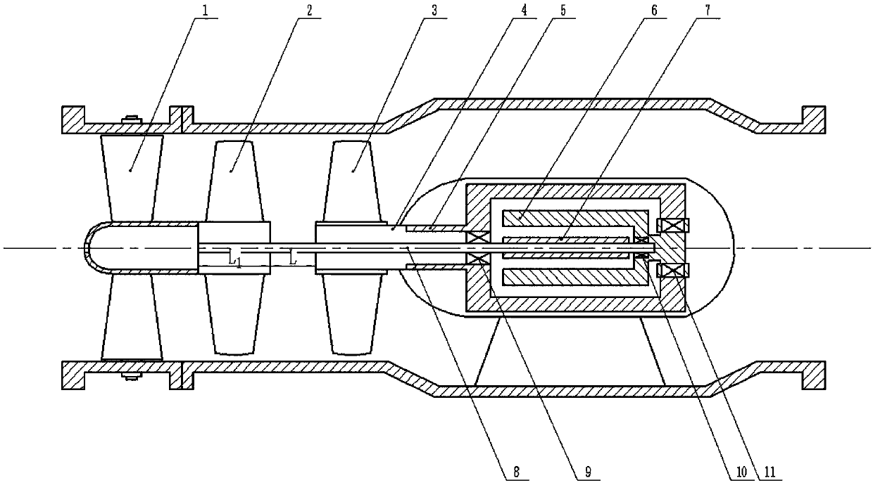
[0028] figure 1 Shown is an embodiment of a multi-working-condition turbine for a tidal power station based on a double-rotor counter-rotating permanent magnet motor of the present invention. The multi-working-condition turbine for a tidal power station based on a double-rotor counter-rotating permanent magnet motor includes movable Guide vane 1, runner one 2, runner two 3, hollow shaft 4, motor rotor one 5, motor stator 6, motor rotor two 7 and inner shaft 8, described turbine mainly consists of front movable guide vane 1, two One counter-rotating runner 2, runner 2 3 and motor part; runner 1 2 and runner 2 3 are installed axially symmetrically, movable guide vane 1 is arranged on the side of the counter-rotating wheel, and the motor part is arranged on the counter-rotating The other side of the wheel; the runner one 2 is connected with the motor rotor two 7 through the inner shaft 8; the runner two 3 is connected with the motor rotor one 5 through the hollow shaft 4; the mot...


PUM


Abstract

The invention belongs to the field of fluid machinery and discloses a tidal power station multi-working-condition turbine based on a contra-rotating dual-rotor permanent magnet motor. The tidal powerstation multi-working-condition turbine based on the contra-rotating dual-rotor permanent magnet motor comprises moving guide vanes, a first rotating wheel, a second rotating wheel, a hollow shaft, afirst motor rotor, a motor stator, a second motor rotor and an inner shaft. The first rotating wheel and the second rotating wheel are mounted in an axially symmetrical manner. The moving guide vanesare arranged on one side of the contra-rotating rotating wheels. The first rotating wheel is connected to the second motor rotor through the inner shaft. The second rotating wheel is connected with the first motor rotor through the hollow shaft. The motor stator is arranged between the first motor rotor and the second motor rotor and is fixed through a second bearing and a third bearing. The innershaft penetrates through the hollow shaft and is fixed through a first bearing and the second bearing. The first motor rotor is fixed through the first bearing and the third bearing. According to thetidal power station multi-working-condition turbine based on the contra-rotating dual-rotor permanent magnet motor, a traditional single-rotating-wheel tidal generator set design is changed into a contra-rotating double-rotor structure, the design is reasonable, the contra-rotating double rotating wheels operate stably, the axial torque is small, and the permanent magnet synchronous motor with the contra-rotating inner and outer double rotors is small in volume and low in vibration.

Description

technical field [0001] The invention belongs to the field of fluid machinery, in particular to a multi-working-condition turbine for a tidal power station based on a double-rotor counter-rotating permanent magnet motor. Background technique [0002] Energy is the foundation and premise of a country's national economic development. Low-carbon, clean and sustainable new energy sources have become an inevitable requirement for social development, and thermal power will still be the main force for power generation in a relatively short period of time in the future. As fossil fuels such as coal and oil become less and less, the proportion of thermal power will gradually decrease, which can be seen from the rising price of coal and oil and the expected proportion of power generation in 2020. Then it will be replaced by new energy power generation without energy consumption and pollution. Because of its reserves and feasibility, hydropower will definitely become the largest part o...

Claims


Application Information

Patent Timeline
Patent Type & Authority Applications(China)
IPC IPC(8): F03B13/00F03B3/12F03B3/18F03B13/26H02K7/18H02K16/02
CPCF03B3/121F03B3/126F03B3/18F03B13/00F03B13/264H02K7/1823H02K16/02Y02E10/20Y02E10/30
Inventor 朱荣生李扬王秀礼司翔宇张国玉
Owner JIANGSU UNIV
Learn More