
Temperature control system of environmental wind tunnel

A technology of temperature control system and wind tunnel, which is applied in the direction of temperature control, control/regulation system, non-electric variable control, etc. It can solve the problem that the change of thermal load cannot be quickly and accurately responded, the temperature control accuracy of the environmental wind tunnel is not high, and the adjustment Low precision and other problems, to achieve the effect of reducing impact, unique variable, and energy saving in system operation

Active Publication Date: 2019-04-05
CHINA ACAD OF AEROSPACE AERODYNAMICS +1
View PDF5 Cites 18 Cited by
  • Summary
  • Abstract
  • Description
  • Claims
  • Application Information

AI Technical Summary

Problems solved by technology

[0004] The process design and adjustment method of the existing environmental wind tunnel temperature control system are not high in accuracy and consume a lot of energy. For example, the high temperature is directly heated by a pipeline electric heater, and the heat exchange cycle system uses more than two two-way control valves. Adjustment, the low temperature uses the low temperature refrigeration system to exchange heat with the brine system to realize the low temperature test, but the cooling water system and the brine system are independent of each other and have no direct heat exchange, which makes the temperature control accuracy of the environmental wind tunnel not high, and the temperature of the environmental wind tunnel test is low. Load changes cannot be quickly and accurately responded to, etc.

Method used


Image

  • Temperature control system of environmental wind tunnel

Examples


Embodiment Construction

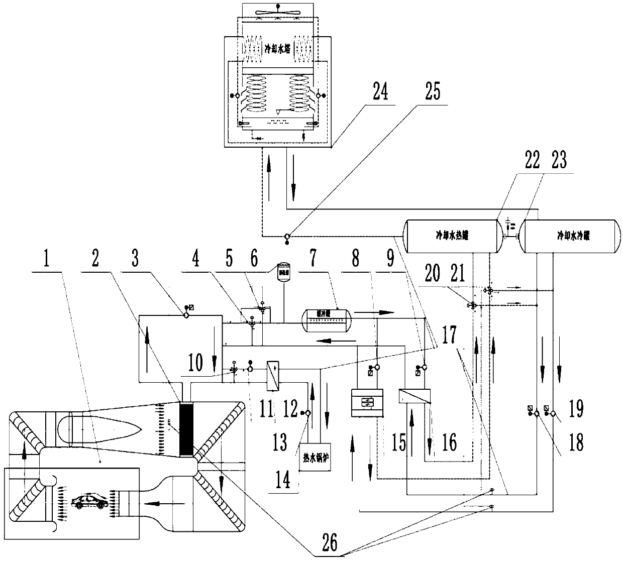
[0024] Such as figure 1 As shown, the environmental wind tunnel temperature control system of the present invention is mainly composed of an environmental wind tunnel 1, a wind tunnel heat exchanger 2, a brine main drive pump 3, a brine cold branch main temperature control valve 4, a brine cold branch auxiliary Temperature control valve 5, constant pressure expansion tank 6, buffer tank 7, brine low temperature drive pump 8, brine normal temperature drive pump 9, brine hot branch temperature control valve 10, brine hot branch drive pump 11, Brine heating heat exchanger 12, hot water driving pump 13, hot water boiler 14, low temperature refrigeration system 15, brine cooling heat exchanger 16, pipeline 17, cooling water brine driving pump 18, cooling water low temperature refrigeration System drive pump 19, cooling water carrier refrigerant temperature control valve 20, cooling water low temperature refrigeration system temperature control valve 21, cooling water hot water tank...


PUM


Abstract

The invention discloses a temperature control system of an environmental wind tunnel, comprising a wind tunnel heat exchanger, a main pipe loop and a plurality of heat exchange branches. The wind tunnel heat exchanger is installed on an expansion section of the wind tunnel. The main pipe loop is a pipeline connecting the inlet and the outlet of the wind tunnel heat exchanger. A plurality of heat exchange branches are connected in parallel to the main pipe loop and can be cycled independently by the main pipe loop. The heat exchange branch comprises a brine circulation unit and a heat exchangecirculation unit. The brine circulation unit comprises a flow-down pipeline, a return pipeline, a drive pump, a three-way valve and a regulating branch. The flow-down pipeline communicates with the main pipe loop and the heat exchange circulation unit, and the three-way valve and the drive pump are sequentially installed along the flow direction on the flow-down pipeline. The return pipeline communicates with the main pipe loop and the heat exchange circulation unit in the downstream of the flow-down pipeline. The regulating branch communicates with the flow-down pipeline and the return pipeline by the three-way valve. The invention adopts the three-way valve to change a blending ratio according to a temperature feedback, the variable is unique, and the adjustment is simple.

Description

technical field [0001] The invention relates to an environment wind tunnel temperature control system, in particular to a temperature control system for automobile environment simulation wind tunnel tests. Background technique [0002] The environmental wind tunnel is mainly used for matching research and development of air conditioning systems and cooling systems of aircraft, automobiles, trains and other means of transportation, thermal management verification and other related test work, to study the influence of different environmental factors on the performance of test products and the system matching optimization of power propulsion systems , to assess the environmental adaptability of the test product. Environmental wind tunnels generally have the ability to simulate climate factors such as high temperature, low temperature, rainfall, snowfall, and sunlight. [0003] The environmental wind tunnel temperature control system is the key system of the environmental wind ...

Claims


Application Information

Patent Timeline
IPC IPC(8): G05D23/20G01M9/02
CPCG01M9/02G05D23/20
Inventor 张建伟易欢石运军黄炳修邓祖国
Owner CHINA ACAD OF AEROSPACE AERODYNAMICS
Learn More